Car Steering Wheel Audio Controls Board - Custom DIY

Thread Starter

travisbklein

Joined Dec 7, 2019
8
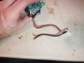
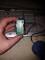
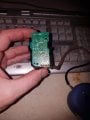
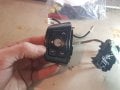
what's up everyone, I pulled this board from an identical car to the one I own (2013 Scion xD) to make custom controls on the other side of the wheel, to do control things like DIY LED interior lights and other things.

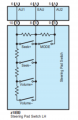
I'm just trying to understand how the board works, I mean I can read it, see all the resistors, but I can't seem to match it up to the circuit diagram provided by the manufacturer. Specifically I can't figure out which wire is giving this board power and where the ground is.

Wire colors from left to right are WHITE, GREY, RED, BROWN. Images are attached.

Thank you so much for any help.


Travis
 

Attachments

Audioguru again

Joined Oct 21, 2019
6,674
The circuit board has simple switches and resistors, no smarts. It drives a computer circuit that does audio control and maybe the light control you want.
Do you have a computer circuit that will control your LED lights from this simple circuit?
 

Thread Starter

travisbklein

Joined Dec 7, 2019
8
Hey whats up and ty so much for the response to help me :)

I will be using an arduino to do the controlling, I just wanted to post here so I could figure out the ground and Vcc and sort of go from there to do the testing on my breadboard.

I spent a few hours figuring out how it exactly worked by following the current (I know a lot longer than you guys who see it right away) the buttons drop down make the connection which fires the wire back to the computer circuit, which in my case would be my arduino, not the stereo in the car.
 

Audioguru again

Joined Oct 21, 2019
6,674
The switches and resistors form an adjustable voltage divider. Feed a DC voltage to pin 8 and pin 10 then the current will change depending on which switch is used.
 

Thread Starter

travisbklein

Joined Dec 7, 2019
8
you have no idea how stupid I feel while asking this, so there are 4 input wires to this circuit, do you know which of the wires would apply to Vcc and which ground?

Just so you know I'm not just going to take whatever answer and move on, I want to understand how you were able to know that, but I am not asking you that, I want to be able to reverse engineer (after I know) so I will learn and be able to do this when I come across switch circuits like this again.

ty ty ty ty ty so much!
 

Audioguru again

Joined Oct 21, 2019
6,674
You must think about how much current will flow if you connect pin 8 and pin 9 or pin 8 and pin 10 across a very powerful car battery. When the top switch is pressed then the current could be hundreds of amps which will cause the wiring and the switch to catch on fire. You need to add a series resistor to limit the current when the switch nearest the pins is pressed and the voltage across that resistor will change by the different current produced by the voltage divider and different switches.
 

Thread Starter

travisbklein

Joined Dec 7, 2019
8
I only see 4 pins :(

There will be no car battery voltage or amps involved, this board will be behind the computer, probably an arduino.
 

bassbindevil

Joined Jan 23, 2014
824
I'd start by marking up the schematic with the values and component designations from the actual circuit board and add the missing stuff like the LED. But, it would also be helpful to take some voltmeter measurements at the connector pins, if possible, with and without the LED lit up. At least if you want to understand the board completely. (Maybe the Mode switch goes to a separate input, so it can act like a "shift" key.) But if you just want to use it as the input to an Arduino and don't need the LED, two wires (to 9 and 10) should be enough: a pull-up resistor to 5V and ground. Then each button press should give a different voltage, and probably Mode will still work as a shift key by altering the voltages each other key produces.
 

Thread Starter

travisbklein

Joined Dec 7, 2019
8
Thank you so much for the reply. Ok I'm going to get started on doing the full diagram, but I am not sure visually what is going on with pin 3. I see pin 2 run up through the bottom 3 resistors, so maybe those 3 resistors are in parallel connected to pins 2 and 3?

When you say "to 9 and 10" do you mean pin 9 and 10 on the arduino? Because I only see 4 pins on this circuit.

Thanks for the help, this is fun!
 

Thread Starter

travisbklein

Joined Dec 7, 2019
8
omg this is so much fun! I just did this for the first time!

Here is how I notated it, (NP) means not pressed, (P) means button pressed. numbers are pins left to right, R numbers are the resistors.

LED - : 1 => R2 => 2
LED +: 3 => R5 => R4 => R3 => LED -

SEEK+ (NP) : 1 => R1 => 2
SEEK+ (P) : 1 => 4

SEEK- (NP) : 1 => R2 => 2
SEEK -(P) : 1 => R6 => 4

VOL+ (NP) : 1 => R1 => 4
VOL+ (P) : 1 => R7 => R6 => 4

VOL- (NP) : 1 => R1 => 4
VOL- (P) : 1 => R8 => R7 => R6 => 4

MODE (NP): 1 => R2 => 2
MODE (P) : 1 => 2

R1, R2 = 100k Ohm
R3, R4,R5 = 700 Ohm
R6 = 330 Ohm
R7 = 680 Ohm
R8 = 2,200 Ohm

Not totally sure what to do next in terms of testing but god damn this was fun ty so much for the help!!!!
 

Thread Starter

travisbklein

Joined Dec 7, 2019
8
Using 1k Ohm resistors as pull up on PIN 2 and PIN 4, left PIN 3 Blank (only for led), Grounded PIN 1.

my source is 5.2v and if you split that into 4 parts guess what , each part is 1.3v! Check out my readings!

PIN 2 , no change except when MODE is pressed and it goes from 5v to 0v, cause of the 100k Ohm resistor

PIN 4
SEEK+ pressed 0v
SEEK - pressed 1.3v
VOL+ pressed 2.65v
VOL- pressed 4.02v
 

bassbindevil

Joined Jan 23, 2014
824
I was referring to 9 and 10 on the schematic diagram, since those were the designations that "Audioguru again" used.

Using two inputs on the Arduino (one digital to read the "mode" switch, one analog to read the seek and vol buttons) sounds like the correct usage. Although... if you were short on inputs, changing the resistor across the "mode" key from 100k to something in the 1K range should allow you to read the keys with a single analog input.
 

Thread Starter

travisbklein

Joined Dec 7, 2019
8
Got ya got ya.

Do you think the mode key being pressed on, on the stock side which turns the stereo off would play a factor.

Obviously with what I am doing it has nothing to do with the stereo but the holding of the mode button I mean, pertaining to the 100k resistor
 
Top