Capacitor size to stop 60hz noise

Thread Starter

PickyBiker

Joined Aug 18, 2015
101
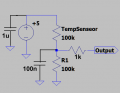
In the temperature sensing circuit below, I am getting some 60 Hz in the output. I would like to place a capacitor to help block that but I have questions Bout capacitor size and location. This sensing circuit is for an Arduino that will use a PID controller to adjust a 3D printer bed heater. The more noise free the temp sensor the better the PID control will work.

1: Should the capacitor be across the output to ground or should it be across the temp sensor which is likely where the noise is being picked up?
2: If it's too small it won't filter adequately and if it is too large it will slow the temperature response. How can I figure out what the capacitance should be?Tmp.PNG
 

ericgibbs

Joined Jan 29, 2010
18,766
hi,
A length of 2.5' is OK, you could use shielded to help reduce mains pickup.
Which type of temperature sensor are you using.?

The problem with removing 60Hz mains hum is the low frequency requires a highish cap value.
What is the lowest response time of tempr change that is acceptable.?

E
 

Thread Starter

PickyBiker

Joined Aug 18, 2015
101
Answering the question on "some" will be difficult without using a scope. What I do know is it varies the calculated temp by about 2-2.5 degrees C.

On the response question, 1-2 degree/second is probably fine because of the mass of the heater bed.

On the type of sensor, it is the standard 100k resistive Temp sensor used in 3D printers.

On the shielded cable, that is a good idea, but I am concerned because the sensor is part of an aluminum heatbed which is probably acting like an antenna for the mains.

Let me know if I can provide any more information about this.
 

ericgibbs

Joined Jan 29, 2010
18,766
hi PB,
Without a scope to measure the suspected 60Hz interference, why do you think its 60Hz.?
It could be electrical noise from a number of sources, is your 5V supply to the Thermistor noisy, try adding say a 1uF across the +5V, close as possible to the sensor,
E
 

Thread Starter

PickyBiker

Joined Aug 18, 2015
101
Here is the temp/voltage readings I got at about room temperature

Temp in C Voltage
20.3 2.33
22.3 2.43
24.3 2.53

looks like .05 V / degree C to me.

I do not know for certain that it is 60 Hz but when I touch near the sensor, the temp varies more so I assumed it is mains being picked up.
 

ericgibbs

Joined Jan 29, 2010
18,766
hi PB,
You could try a simple filter as per this diagram.
Increase the C value as required, depends upon the response time required for the Tempr.
E
 

Attachments

Thread Starter

PickyBiker

Joined Aug 18, 2015
101
Ericgibbs, I understand about the two capacitors but I'm not sure about the purpose of the 1k resistor in the output. Can you provide a little insight?
 

ericgibbs

Joined Jan 29, 2010
18,766
hi,
If the Arduino is switched Off and its a high value cap, it is to reduce the pins input current.
Have you tried the filter.
E
 

Thread Starter

PickyBiker

Joined Aug 18, 2015
101
Thanks, I understand now. I have not tried the filter yet. I am changing to a shielded cable (as soon as I can find that in my raw materials or order some.) and the filters you suggested will be added too.
 

MrSoftware

Joined Oct 29, 2013
2,188
You can oversample the ADC line and average as mentioned above. Not a fix, but it could help. Without a scope you might be able to determine the frequency of your noise using your ADC. Take a couple seconds worth of samples as quickly as you can sample then graph the results. Dump it to a text file and graph it with google sheets or excel, etc.. If the noise frequency is low relative your sample rate, you should see the noise frequency in the graphed results. Note that if your only means of output from the arduino is the terminal, then take your samples first and put them in a buffer, THEN dump the output to the terminal after your sampling is completed. This will significantly increase your ability to sample quickly.

If you need to add capacitance, I believe you'll get the best results by adding it as closely to the temp sensor as possible. Also if you can incorporate some sort of differential line driver for the temperature signal then that could possibly help a lot as well.
 
Last edited:

Thread Starter

PickyBiker

Joined Aug 18, 2015
101
ericgibbs, Great minds think alike. I am trying a filter that works by keeping track of the last calculated value and then letting a new values change the result by a small percentage. Right now I have set the function to 95% dependent on the saved old value and 5% on the new value. Once calculated, the result is stored as the lastTemp. So far, that appears to be working quite well. Here is what that looks like in Arduino code where data is the new temp and gain is the % of reliance on the lastTemp. In the setup, I get the temperature once to set lastFiltered so it doesn't start out at 0.

double filtered, lastFiltered;

double Filter(double data, double gain)
{
filtered = (lastFiltered * gain) + (data * (1 - gain));
// Serial.print(" Filtered "); Serial.print(filtered); Serial.print(" ");
lastFiltered = filtered;
return filtered;
}
 

MrSoftware

Joined Oct 29, 2013
2,188
The problem with this approach is that your readings are inaccurate due to noise and you're smoothing the output in an attempt to hide the inaccuracies. The better approach is to make the readings more accurate, though you would know more than we would if your use case requires better accuracy or not.
 

Thread Starter

PickyBiker

Joined Aug 18, 2015
101
This appears to be resolved now. I added a 1uf electrolytic capacitor from the sensor lead to ground. I also used shielded cable for the sensor leads from the heat plate to the Arduino. That brought the temp variation down to .7 to .9 degrees C and it is still responds plenty fast enough to work in this application. I added the software filter at 95% and that brought it down to almost nothing and it still responds fast enough. . I have a very stable temp reading now. Time to work on my PID control.

Thank you all for the suggestions and help.
 

Andrei Suditu

Joined Jul 27, 2016
52
You could use an RC filter with a cutoff way lower than 60hz.
Try a 220ohm resistor and a 47uF cap.
Cutoff would be at ~15Hz.
If does not work good enough lower the cutoff freq by increasing R.
If not good enough try other sensing method.....like Supply the resistor with a constant current and measure the voltage.
REF 200AU is a constant cuurent source of 100uA.Your 100k val of the sensor is a bit high since it will give 10V and will probably need buffering in your configuration since when you will measure with an ADC it will pull the voltage a bit down.
So try a CC source and read the value affter you buffer it with an opamp voltage buffer.
 
Top