 Facebook
 Google
 GitHub
 Linkedin
Hi All,
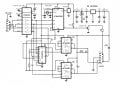
I need some help in an attempt to understand a schematic (attached). In the top right corner is a 12V-to-5V MC78M05 voltage regulator. What I don't understand is why they have so many parallel capacitors there? C7 and C8 on the output side and C9 and C10 on the input? Based on the IC reference the input side only needs 0.3uF and the output 0.1uF. I assume they added the electrolytics to add stability in case 12V source isn't stable enough? If that's the case, why is C9 still needed, can't it be replaced by C10?
Also, is the component placement critical, for example, when designing the board, can we move C8 next to C3 for example?
Sorry for the noob questions and thanks in advance!
Attachments
-
 87.5 KB Views: 34


