Capacitor calculations in split rail design

Thread Starter

FuneralHomeJanitor

Joined Oct 12, 2019
64
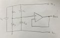
For this circuit, which I saw a long time ago and redrew, I am making a split rail power supply and trying to make my own calculations based on what values I have on hand and am I wrote node equations but am stuck when dealing with the capacitors. Would they be treated like reactances with the frequency set for 60 Hz to filter power supply noise? Or do they require thevenin theorem with time constants/differential equations? I understand that they should charge quickly and behave like open circuits in that scenario, but would like to do the actual calculations for it. These are my thoughts but I could definitely be wrong about both of these, so anyone that can help, know it will be appreciated
 

Attachments

WBahn

Joined Mar 31, 2012
32,703
Their value is pretty non-critical and 0.1 µF is probably a good starting point. Trying to nail down specific values, or even min/max values, you would need to know more about your system, such as the spectral characteristics of the noise you are trying to suppress.

If your Vs is not very stable, then you probably want to put some capacitance directly across it to lock it down a bit better. You would likely find that you don't need the capacitors across each of the voltage divider resistors. Depending on where Vs is coming from and what you are doing with your split supplies, you might also find that you are better off with just one of those capacitors and not both. Using only one will tend to move the noise to one of your split supplies while keeping the other a bit cleaner, you can then design your circuit to exploit this.
 

Ian0

Joined Aug 7, 2020
13,097
If your signal is going to be re-referenced to the negative supply at the output, or is referenced to the negative supply at the input, then one capacitor from the half-supply rail to ground will be better. With two capacitors the ripple on the positive supply will be divided by two rather than filtered out.
Actual values don't matter very much as you can use quite a large value of resistor, but, obviously, keep the cutoff frequency 1/(2πRC) well below the ripple frequency.
If you use too large a value of resistance, op-amp bias currents could move the half-supply rail away from the centre, but that won't actually matter very much.
 

Thread Starter

FuneralHomeJanitor

Joined Oct 12, 2019
64
Thank you for all of the responses. I had a feeling the value wouldn’t matter too much, but would the actual value be calculated based on the frequency of the noise measured in the circuit?
 
Top