Facebook
 Google
 GitHub
 Linkedin
Hai.,
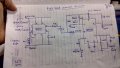
I have used a combination of LM331 and 555 timer circuit to measure the Capacitive value that i get across the sensor ,The output i get from the sensor comes with a variation Difference of around 1.8V (Level 0 to 70)and the Output voltage i am getting is in multimeter is Constant with the variation on fuel level.,
My issue i am facing is.,
1)when i connect the output voltage to Arduino(Analog) to read it in serial monitor i am not getting the exact value as i am getting in Multimeter?
I get a constant value in multi meter where as i don't get that value in the Arduino.,IT shows the wrong voltage and it keeps on oscillating(It even Drops to 0 certain times)
Last edited: