Can't run MOSFET in half bridge configuration

Thread Starter

Siddharth Singh 3

Joined Jun 17, 2019
24
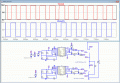
Hi! I am working on switching of MOSFET. I tried to run the mosfet in half bridge configuration. The simulation got stuck at 0.4%. I am switching the mosfet at 100 kHz frequency. I was able to drive the mosfet alone (in boost converter circuit). But when I tried to drive the mosfet in half bridge configuration, I could not run it. The gate driver I am using is ACPL 337J (Datasheet- https://www.mouser.com/datasheet/2/678/V02-4390EN_DS_ACPL-337J_2014-05-09-909393.pdf). The mosfet I am using is STF27N60M2-ep (Datasheet- https://www.st.com/resource/en/datasheet/stf27n60m2-ep.pdf). The schematic of boost converter circuit is - aae.JPG

Please find the attached schematic (LTspice) of boost converter circuit (Draft 29).
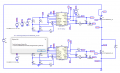
I implemented this circuit in half bridge configuration.-
aae2.JPG

Please find the attached schematic of half bridge configuration (Draft 30).

Please help me pointing out where I am doing it wrong. Also please upload the corrected schematic.
Please find the attached library of mosfet.
 

Attachments

ci139

Joined Jul 11, 2016
1,898
100 kHz frequency
Spice trivia :
try more relaxed PWM rise/fall times --and/or-- adding a reasonable series resistance to
  • PWM
  • Vs
  • Large ballast/smoothing capasitors
? put a diode (in front) in series with L1 300µH
(+perhaps C(<0.1uF) --or-- RC(in series) in parallel with M1.drain - source)

-- the Spice don't like too high ("unlimited") instantaneous currents & frequencies

(sometimes adding the 1N4148 or UPSC600 reverse to G-S terminals of the MOS-Fet let's you run a complex circuitry)
 

ericgibbs

Joined Jan 29, 2010
18,848
Hi S,
Combined all the models, but look at this clip, when I try to run it, you have embedded the ACPL lib in your folders and I cannot access it to change to my folder.
If the lib path was on the circuit diagram I could edit to suit my folders.
E
You see I have changed the STF pointer OK.
 

Attachments

Thread Starter

Siddharth Singh 3

Joined Jun 17, 2019
24
Hi S,
Combined all the models, but look at this clip, when I try to run it, you have embedded the ACPL lib in your folders and I cannot access it to change to my folder.
If the lib path was on the circuit diagram I could edit to suit my folders.
E
You see I have changed the STF pointer OK.
If you have downloaded the SPICE model of ACPL-337J, open the spice model and right click on the command-
".subckt ACPL-337J VEE1 VIN+ VCC1 VLEDDRV UVLO_B FAULT_B ANODE CATHODE"
Go to create symbol. LTspice will ask if you want to automatically create the symbol from netlist. Click yes.
The acpl 337j symbol is generated in your library. Now click add new component. There you will find a folder named [AutoGenerated]. Open the folder. There is your acpl 337j optocoupler sitting.
Similarly, if the STF file is working then ok. If not then follow this:-
Go to Edit-> SPICE Directive'S'. Click on it. A new dialogue box will open. Write ".lib" and press OK(make sure it is selected on SPICE directive). Plce this .lib on anywhere on board. Now right click on this .lib text. click browse and select the library file.
Go to the mosfet and press Ctrl+right click. Change the prefix to X and Value to STF27N60M2-EP_V2. Click OK.
There you are all set to use the schematic
 

ci139

Joined Jul 11, 2016
1,898
Code:
* Copyright 2014 Avago Technologies Limited. All Right Reserved
*
* ACPL-337J Spice Macromodel
* Rev.A
* 1/14
*
* SPICE Model is verified by Orcad PSpice at Ta=25^C.
one of the problems may be using the Pspice model
. . . the more simple models may be easier to adjust for LT - difficult ones require skills i don't yet have . . .

↑↑↑ = try running one of these iC-s in it's factory recommended test circuit - see if it does anything

other (fast) options may be
  • don't step the sources at startup if you do --or-- step 'em if you don't
  • use alternate Solver if you use Normal --or-- the way around
  • introduce 2Ω resistance to your supplies ( perhaps with ≥ (330/)470µF "ballasts")
  • etc.
 
Last edited:
Top