Here is a small portion from the tutorial on POWER and GROUND connections of the components...
"EAGLE, by default, assumes that all active components will be attached to the same power source and ground. The power pins are therefore not shown, and are automatically connected to the Power Source and Ground when generating a board (unless the user connects them to other signals). Use the INVOKE command in case you want to place it in the schematic.
Most of the EAGLE library devices, which have only one VCC and one GND
pin, are defined so that the power pins, by default, are not visible. In some cases it makes sense to make the power pins in an IC visible, as in the 555N stored in the linear library. In such a case connect the power pins with the appropriate nets."
I don't know what version EAGLE is on now but it may still be similar to this earlier document.
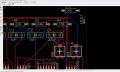
Let me start by saying, I haven't used EAGLE in a long time. The symbols you are using for your supplies look to me like an "off page" type of connection. If you change it to a true supply type connection, which can be a small triangle or single arrow, you might not get the error. I don't have EAGLE on this machine so I can not direct you to the different symbols more specifically.
Also, do not connect the outputs of the unused comparators and logic gates to ground.
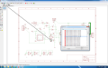
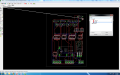
could anyone give me the basics of routing the board manually. what do i have to look out for and what are the normal industry standards. my board is pretty standard. Could anyone help me with how many layers i would need. there is only one channel i would need AC 220V passing though at the relay connection. so what kind of channels should I use. and what about vias? I am gettin an error as shown below while using the auto route feature.
thanks in advance.
Let me start by saying, I haven't used EAGLE in a long time. The symbols you are using for your supplies look to me like an "off page" type of connection. If you change it to a true supply type connection, which can be a small triangle or single arrow, you might not get the error. I don't have EAGLE on this machine so I can not direct you to the different symbols more specifically.
Also, do not connect the outputs of the unused comparators and logic gates to ground.
Hmmm, I regularly place the unused comparators outputs to ground, it does nice things to the board layout. A LM393 can have pins 1,2,3, and 4 all grounded with no problem. Eagle will not allow this?
Hmmm, I regularly place the unused comparators outputs to ground, it does nice things to the board layout. A LM393 can have pins 1,2,3, and 4 all grounded with no problem. Eagle will not allow this?
When I first looked at the schematic and wrote the reply I assumed they were opamps. I made the comparator change at the last second without thinking about the open collector outputs...
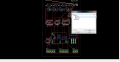
It is still showing the errors. I do not know about the keep out areas. how do i find out about those. plus there is no connection between the led and anything on the board. the autoroute did not connect the led to anything. any idea why?
 Facebook
 Google
 GitHub
 Linkedin
 272.2 KB Views: 418