Can you help me read this schematic?

Thread Starter

sofasurfer

Joined Jun 16, 2023
7
I have an electric winch. Its a cheap Harbor Freight winch with wireless remote, but is all I need (till it broke).
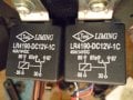
It stopped working with the remote. The motor works with a direct connect to power source but I can get no activity through the relays. I opened the relays and found one of them burned up inside. I include a photo of relays.
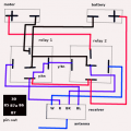
I also include a schematic I made of the wiring. I am going to pick up a new relay tomorrow. I'm also going to pick up an in line circuit breaker.
The relay on the left is the one that burned up.

1) Would the bad relay prevent all power flow in the good relay also? Just wondering if it is obvious that this is the whole problem or if the remote receiver may also be bad.
2) Can you ID what the wires to the receiver do (power in, out, forward, reverse) in case I also need a new remote receiver?
3) Is it possible to explain to me the power flow and thus, how it works?

I have no problem reading a single relay but two relays is very confusing to me?
Thank for whatever help you can give me.
 

Attachments

SamR

Joined Mar 19, 2019
5,470
Welcome to AAC!
What you have is a wiring diagram and not a true circuit schematic. Not much help without a schematic. Is the antenna still in place?
 

Thread Starter

sofasurfer

Joined Jun 16, 2023
7
Yes, antenna is in place. Its just a wire attached to the board. What else do you need? The only thing other than the wiring diagram is the relay inerds and that is shown on the relay photo. Being a Harbor Freight product there is no other info available.
 

Irving

Joined Jan 30, 2016
5,001
The circuit is a simple forward/reverse arrangement. When both relays are off no power is applied to the motor as both sides of the motor are connected to battery -. When either relay is activated one or other side of the motor is connected to battery + and the motor runs in that direction.. The remote connections are black -, red + , white & blue I guess correspond to the IN/UP & OUT/DOWN buttons, but can't say which is which.

1688329583128.png
 

SamR

Joined Mar 19, 2019
5,470
You said the winch worked, just not the remote control. I'd be looking at the remote control as the most likely source of your problem. Especially if the antenna is still attached to the winch unit.
 

Thread Starter

sofasurfer

Joined Jun 16, 2023
7
Ok. I'll see what I can find out. Thanks.
Is that wiring diagram you posted a reworked duplicate of mine or your own diagram? It sure is a better job than what I did and I spent about 3 hours doing mine. Thanks, that teaches me a lot.
 

Irving

Joined Jan 30, 2016
5,001
Ok. I'll see what I can find out. Thanks.
Is that wiring diagram you posted a reworked duplicate of mine or your own diagram? It sure is a better job than what I did and I spent about 3 hours doing mine. Thanks, that teaches me a lot.
Its a proper schematic based on your wiring diagram. Some people have difficulty assessing or mentally translating a physical construct to a schematic representation. A schematic, if properly laid out, does make it easier to understand the purpose of a circuit. In this case, for example, just seeing the motor connected to the common pole of both relays is an immediate clue to the forward/reverse nature of the circuit, which is not so obvious from the wiring diagram unless you use automotive relays and know that '30' is the common pole.
 

MisterBill2

Joined Jan 23, 2018
27,187
A wiring diagram is helpful for connecting or re-assembling a system. It is NOT very useful for understanding how a system functions.
My guess is that the relay that burned up is the one for the "retract" direction, because that will have the highest load current. Repeated rapid starts, as when positioning something with a winch, will lead to contact over heating in motor control relays. Then they burn up.
With the circuit shown, both relays need to carry current no matter which direction is used. So replacing the failed relay may totally fix the failure. So you might be quite fortunate there.
 

SamR

Joined Mar 19, 2019
5,470
What is missing is the schematic of the wireless transmitter and receiver which controls the relays as well as the manual controls he said did work.
 

crutschow

Joined Mar 14, 2008
38,325
If a relay is bad, then adding a rectifier bridge across the motor between V+ and V- (below) would minimize the inductive spikes across the relay contacts when they open and should prolong their life.
The diodes limit the voltage across the contacts to the supply voltage plus two forward diode-drops, to carry the inductive motor current when the contacts open, and prevent arcing while the current dissipates.

A 3A bridge rectifier should be adequate for this application, as the diodes only have to carry a short pulse of current when the contacts open, which should be under their surge-current rating.

1688396055937.png
 
Last edited:

MisterBill2

Joined Jan 23, 2018
27,187
My impression was that what worked was a direct connection of the motor to power, not a local manual control. And my guess is that what led to the failure of whatever relay was a rapid string of starts in the same direction, as in getting something into exactly the right position. Therelay may mot have survived the heating from the repeated inrush current starts. Just because a relay is rated for a max load current does not mean it is good for a whole fast string of full load starts.
 

Irving

Joined Jan 30, 2016
5,001
What is missing is the schematic of the wireless transmitter and receiver which controls the relays as well as the manual controls he said did work.
The internals of the transmitter and receiver are, IMHO, moot as these are standalone modules - IMHO they had little bearing on the failed relay.

The manual buttons would parallel the White and Blue wires from the remote receiver to battery -ve (black wire).
 

MisterBill2

Joined Jan 23, 2018
27,187
The original wiring diagram does not show any wired manual buttons, and I have not see those on any wireless winch. Consider that when using a front mounted winch to get a vehicle out of "a bind", standing near the winch is a poor choice.
ALSO. the TS mentioned that a direct battery connection ran the motor correctly, while using the relays did not.
Based on that information there is no reason to suspect the remote receiver as being the problem. In addition, the statement that "one of the relays was burned up inside" points at a very obvious suspect, especially given the circuit schematic that we have.
Once again, the likely cause is rapidly repeated starts, in one direction, under a heavy load. This style of relay does not have much mass close to the moving contact to draw heat from the contact. In addition, if the return spring was not strong enough, a weak contact pressure could certainly lead to overheating.
So my suggestion is to use a better quality relay from a better manufacturer as a replacement. There is a fair quality spread among products that have the same form factor and an identical connections arrangement .
 

Tonyr1084

Joined Sep 24, 2015
9,744
If one relay has burned up then the other may be close behind. Keep in mind, those relays are rated for 40 amp service. As @MisterBill2 said, repeated tapping of the remote will rapidly trigger the relay. Every time the motor starts it's going to have an inrush of current. That may be the reason for the failure. The remote is a moot point as @Irving said. It could not be responsible for the relay failure unless the remote was operated too far for a good signal. A weak signal may have resulted in a rapid fire trigger of the failed relay, but aside from that possibility (or a weak battery) I wouldn't expect to find any issues with the remote. I believe I have the same wench. I use mine to pull lumber from street level to the second floor and vice versa with finished projects that are too large to carry down stairs.
 

MisterBill2

Joined Jan 23, 2018
27,187
Abuse of one relay that leads to failure may not reasonably be assumed to mean that the other is close to failure also. If the hoist load in lifting is large that does not mean that the load in lowering is also large. The probable cause of failure was exceeding capabilities, not normal wear. so I hold that the assumption that the other relay is also worn almost to failure is not reasonable.
 

Tonyr1084

Joined Sep 24, 2015
9,744
Maybe not. Of course one could wait till IT fails - if it does. Or one could replace it now and avoid an inconvenient problem later.
 

MisterBill2

Joined Jan 23, 2018
27,187
We await a report from the TS as to the effectiveness of replacing the failed relay.
And one more thought, based on the circuit diagram, is that the diodes are not required because when both relays are released the motor is short circuited. It is difficult to generate much of a transient spike across a short circuit.. At least that has been my experience.
 
Top