Can you help designing this buffer?

Thread Starter

sonohe

Joined Jan 11, 2025
63
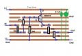
I would like to make this circuit on stripboard. This is actually a buffer on the input in one of the Boss pedals, with some modification, so that the signal leaving the circuit is reduced with 50% in the end.

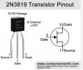
On the photo below, on the left side, you can see the original buffer circuit from Boss, on the right side it is the modified design (the blue circle is the transistor).

I wondered if someone could help me convert it to stripboard design? I cannot do that myself, my knowledge is too little for that.

buffer2.jpg
 

Thread Starter

sonohe

Joined Jan 11, 2025
63
Appears you already have from the drawing.
No I don't. I don't know how to convert it to stripboard. I am not familiar with the routing solutions on stripboard that is a different concept than the one you see. That's why I am asking.
 

Thread Starter

sonohe

Joined Jan 11, 2025
63
I have seen that guide. But as I am a total beginner, I have no clue about the basics of electronics, so I have no clue about routing. This guide you link shows some routing solutions, but does not show others. And to build stripboards, it is the routing that is essential. The components and their direction is marginal, that is already on the diagram. But routing is different. If you can link a guide that enlists routing situations from diagrams and how to apply that on stripboard, that would be the real help. Sadly I have not found any.


See this image below. I encircled the routing situations with red that I would like to see how they look on stripboards. If I could see them I would understand everything and could start building:

routing2.JPG
 

sarahMCML

Joined May 11, 2019
695
Here's my version of your circuit. It doesn't look like yours, but it would work identically. I haven't cut any tracks to shorten them, as would normally be done, because I don't wish to waste the stripboard. But in this case there are no parts of the circuit which interact.

The 47nF capacitor is an old one which straddles 5 tracks, so does go to the gate of the FET. The 100uF capacitor across the lower 10k resistor has its positive pin stretched to reach, just for simplicity. You could solder it in where it fits, and take a wire jumper to the common point of the resistors!
Obviously, you would build your circuit on the other side of the board!

Edit: I made an error on my layout, will redo later!

Back again: Here is the board layout, plus I edited some of the above text as well. If you just follow the components from input to output, you should get the idea that the layout doesn't have to be exactly like the schematic.

Vero_Board.png
 
Last edited:

Thread Starter

sonohe

Joined Jan 11, 2025
63
Thank you very much! Please give me a day to check this, I already have some questions.

Also I have another circuit version that I can do myself now as I can see the routing from yours. Besides I figured out another technique myself as well, an unusual way but I think it might work. I will create the plan myself for that let me ask you to check that too, just give me some time to post it.
 

Thread Starter

sonohe

Joined Jan 11, 2025
63
Sonohe, please see my previous post.
Sarah!

I have another version of the circuit, you sent me the stripboard design for. I transformed to other one to stripboard design myself. I want to build both to see which one is better. May I as you to check the other one whether it is correct?:
55100.pngThis is it on stripboard:
Buffer.png
 

sarahMCML

Joined May 11, 2019
695
It is mostly functionally fine, if a little too spread out possibly. However, the gate of the FET needs to go down one track, to the common point between R2 and C1. R1's leads can stretch across from its C1 end to the R4 ground, doing away with the blue jumper wire. If you build it, cut the tracks after the soldered components to eliminate unused sections. This helps to avoid stray pickup.
 

MisterBill2

Joined Jan 23, 2018
27,187
I suggest standing the transistor a bit farther up from the board. That is a way to avoid transistor physical damage when it gets bumped over. Mechanical abuse accidents do happen, at least they happen to me a bit.
 

sarahMCML

Joined May 11, 2019
695
What about the specs for the resistors and the C1 capacitor written at the bottom? Those are my own ideas, are those correct?
I personally wouldn't use a ceramic capacitor for audio coupling, because they can be a little noisy, but if that is all you have... The resistor wattages are fine, given the low power dissipated in them.
As MisterBill2 notes, you could relocate the Drain of the FET down to a lower track to take the strain off of that leg. I'd move it to the same track as the Gate, and cut the track between the two sections.
 

Thread Starter

sonohe

Joined Jan 11, 2025
63
As MisterBill2 notes, you could relocate the Drain of the FET down to a lower track to take the strain off of that leg. I'd move it to the same track as the Gate, and cut the track between the two sections.
But if you remove the Drain from the top stripe were will the 9V electricity enter into the circuit? The power will be cut off from the circuit.

If not ceramic, what type of capacitor should I use?
 

sarahMCML

Joined May 11, 2019
695
But if you remove the Drain from the top stripe were will the 9V electricity enter into the circuit? The power will be cut off from the circuit.

If not ceramic, what type of capacitor should I use?
If you move it down to the same track as the gate, and cut the track between the two, you can then connect the +9V to the same side of the track that the drain is now connected to.
Use a plastic type capacitor, such as polyester, unless it's in the uF range, in which case it would probably be an electrolytic.
 
Top