 Facebook
 Google
 GitHub
 Linkedin
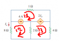
i'm trying to solve this problem using mesh analysis but i'm stuck. clearly we have 3 meshes and there are current sources in common between mesh 1 and mesh 2. and between mesh 1 and mesh 3 so we have to make a super-mesh. the problem is, when i remove the 4A source (the one between mesh 1 and mesh 2) i'm left with the the 2Io source connected in series with the 2ohm resistor. should i remove them too and make a super-mesh that spans the whole circuit or what?
Attachments
-
 13.5 KB Views: 19


")


