Can´t interface PIC18F4520 to LCD HD44780

Thread Starter

LewisMF

Joined Nov 15, 2014
100
Hi everybody,

I am trying to interface a PIC18F4520 to a standard 16x2 LCD with Hitachi HD44780 controller in 4-bit mode, I am using MPLAB IDE v2.35 with C18 compiler.

This is my code:

Code:
/*Libraries*/
#include <stdio.h>      //standard I/O library
#include <stdlib.h>     //standard library
#include <xlcd.h>       //LCD library
#include <delays.h>     //Delays library
#include <p18f4520.h>   //PIC18F4520 library

/*Fuses*/
#pragma config OSC = HS,FCMEN = OFF,IESO = OFF
#pragma config PWRT = ON,BOREN = OFF,BORV = 0
#pragma config WDT = OFF,WDTPS = 32768
#pragma config MCLRE = ON,LPT1OSC = OFF,PBADEN = OFF,CCP2MX = PORTC
#pragma config STVREN = OFF,LVP = OFF,XINST = OFF,DEBUG = OFF
#pragma config CP0 = OFF,CP1 = OFF,CP2 = OFF, CP3 = OFF
#pragma config CPB = OFF,CPD = OFF
#pragma config WRT0 = OFF,WRT1 = OFF,WRT2 = OFF
#pragma config WRTB = OFF,WRTC = ON,WRTD = OFF
#pragma config EBTR0 = OFF,EBTR1 = OFF,EBTR2 = OFF
#pragma config EBTRB = OFF

/*Delays for LCD - All calculated for Xtal=20MHz*/
void DelayFor18TCY(void)
{
    Delay10TCYx(10); //Delay of at least 18 Clock Cycles
}

void DelayPORXLCD (void)
{
    Delay1KTCYx(80);    // Delay of at least 15ms
}

void DelayXLCD (void)
{
    Delay1KTCYx(10);    // Delay of at least 5ms
}

/*Main Program*/
void main (void){

    ADCON1=0x0F;    //All I/O as digital
   
    OpenXLCD(FOUR_BIT & LINES_5X7); //Four bit mode and 5x7 lines
    while(BusyXLCD());
    WriteCmdXLCD(CURSOR_OFF & BLINK_OFF);

    while (BusyXLCD());         //Wait for LCD
    putrsXLCD("PIC18F4520");    //Output message to LCD

    while(1){};     //Infinite loop
}
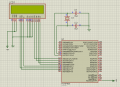
Attached you will find a screenshot of my schematic.

I am simulating it in ISIS with an XTAL of 20MHz, when I simulate the data pins for the LCD appear disconnected and the LCD is blank.

Can anyone spot the mistake?

Thanks in advanced for any help.
 

Attachments

ErnieM

Joined Apr 24, 2011
8,377
Check the data sheet of the HD44780 (or clone) controller you are using. Typically there is a delay after power up before any commant, and after the opening command too.

Make sure your copy of XLCD has these delays properly sey up.

Did you make a custom xlcd.h file? I believe that is where the library leans what pins your functions are on.
 

Thread Starter

LewisMF

Joined Nov 15, 2014
100
Check the data sheet of the HD44780 (or clone) controller you are using. Typically there is a delay after power up before any commant, and after the opening command too.

Make sure your copy of XLCD has these delays properly sey up.

Did you make a custom xlcd.h file? I believe that is where the library leans what pins your functions are on.

Hi ErnieM,

I am using standard xlcd.h file, I haven´t made any modifications.

I programmed the delays in the main C file as described in the datasheet.

This is the xlcd.h file, as you can see there has been no modifications (I actually tried to modify it and it doesn´t let me, it says "access denied" I dont really understand why)
Code:
#ifndef __XLCD_H
#define __XLCD_H
#include "p18cxxx.h"
/* PIC18 XLCD peripheral routines.
*
*   Notes:
*      - These libraries routines are written to support the
*        Hitachi HD44780 LCD controller.
*      - The user must define the following items:
*          - The LCD interface type (4- or 8-bits)
*          - If 4-bit mode
*              - whether using the upper or lower nibble
*          - The data port
*              - The tris register for data port
*              - The control signal ports and pins
*              - The control signal port tris and pins
*          - The user must provide three delay routines:
*              - DelayFor18TCY() provides a 18 Tcy delay
*              - DelayPORXLCD() provides at least 15ms delay
*              - DelayXLCD() provides at least 5ms delay
*/

/* Interface type 8-bit or 4-bit
* For 8-bit operation uncomment the #define BIT8
*/
/* #define BIT8 */

/* When in 4-bit interface define if the data is in the upper
* or lower nibble.  For lower nibble, comment the #define UPPER
*/
/* #define UPPER */

/* DATA_PORT defines the port to which the LCD data lines are connected */
#define DATA_PORT              PORTB
#define TRIS_DATA_PORT         TRISB

/* CTRL_PORT defines the port where the control lines are connected.
* These are just samples, change to match your application.
*/
#define RW_PIN   LATBbits.LATB6           /* PORT for RW */
#define TRIS_RW  TRISBbits.TRISB6        /* TRIS for RW */

#define RS_PIN   LATBbits.LATB5           /* PORT for RS */
#define TRIS_RS  TRISBbits.TRISB5        /* TRIS for RS */

#define E_PIN    LATBbits.LATB4          /* PORT for D  */
#define TRIS_E   TRISBbits.TRISB4        /* TRIS for E  */

/* Display ON/OFF Control defines */
#define DON         0b00001111  /* Display on      */
#define DOFF        0b00001011  /* Display off     */
#define CURSOR_ON   0b00001111  /* Cursor on       */
#define CURSOR_OFF  0b00001101  /* Cursor off      */
#define BLINK_ON    0b00001111  /* Cursor Blink    */
#define BLINK_OFF   0b00001110  /* Cursor No Blink */

/* Cursor or Display Shift defines */
#define SHIFT_CUR_LEFT    0b00000100  /* Cursor shifts to the left   */
#define SHIFT_CUR_RIGHT   0b00000101  /* Cursor shifts to the right  */
#define SHIFT_DISP_LEFT   0b00000110  /* Display shifts to the left  */
#define SHIFT_DISP_RIGHT  0b00000111  /* Display shifts to the right */

/* Function Set defines */
#define FOUR_BIT   0b00101100  /* 4-bit Interface               */
#define EIGHT_BIT  0b00111100  /* 8-bit Interface               */
#define LINE_5X7   0b00110000  /* 5x7 characters, single line   */
#define LINE_5X10  0b00110100  /* 5x10 characters               */
#define LINES_5X7  0b00111000  /* 5x7 characters, multiple line */

#define PARAM_SCLASS auto
#define MEM_MODEL far  /* Change this to near for small memory model */

/* OpenXLCD
* Configures I/O pins for external LCD
*/
void OpenXLCD(PARAM_SCLASS unsigned char);

/* SetCGRamAddr
* Sets the character generator address
*/
void SetCGRamAddr(PARAM_SCLASS unsigned char);

/* SetDDRamAddr
* Sets the display data address
*/
void SetDDRamAddr(PARAM_SCLASS unsigned char);

/* BusyXLCD
* Returns the busy status of the LCD
*/
unsigned char BusyXLCD(void);

/* ReadAddrXLCD
* Reads the current address
*/
unsigned char ReadAddrXLCD(void);

/* ReadDataXLCD
* Reads a byte of data
*/
char ReadDataXLCD(void);

/* WriteCmdXLCD
* Writes a command to the LCD
*/
void WriteCmdXLCD(PARAM_SCLASS unsigned char);

/* WriteDataXLCD
* Writes a data byte to the LCD
*/
void WriteDataXLCD(PARAM_SCLASS char);

/* putcXLCD
* A putc is a write
*/
#define putcXLCD WriteDataXLCD

/* putsXLCD
* Writes a string of characters to the LCD
*/
void putsXLCD(PARAM_SCLASS char *);

/* putrsXLCD
* Writes a string of characters in ROM to the LCD
*/
void putrsXLCD(const rom char *);

/* User defines these routines according to the oscillator frequency */
extern void DelayFor18TCY(void);
extern void DelayPORXLCD(void);
extern void DelayXLCD(void);

#endif
This is driving me crazy, I can´t find any examples anywhere and I don´t really understand why it doesn´t work.

Any more suggestions?

Thank you for your help ErnieM.
 

MaxHeadRoom

Joined Jul 18, 2013
28,617
This is driving me crazy, I can´t find any examples anywhere and I don´t really understand why it doesn´t work.

Any more suggestions?

Thank you for your help ErnieM.
There is example files on the Picmicro site both C and assy.
The files supplied with Picdem2 Plus Demo board are on the Picmicro site.
Max.
 

ErnieM

Joined Apr 24, 2011
8,377
The xlcd.h you included seems to match your hardware. Is the file read only?
Check the data sheet of the HD44780 (or clone) controller you are using. Typically there is a delay after power up before any commant, and after the opening command too.
I saw you have delays defined in your code. I do not see where or if they are used. Did you check if the starting delays are in the library?

Since I have never used ISIS I can't comment further. If you actually build one I would have suggestions (like make sure the pins wiggle when you want them to).
 

Thread Starter

LewisMF

Joined Nov 15, 2014
100
There is example files on the Picmicro site both C and assy.
The files supplied with Picdem2 Plus Demo board are on the Picmicro site.
Max.
Hi Max,

I have been checking the
The xlcd.h you included seems to match your hardware. Is the file read only?

I saw you have delays defined in your code. I do not see where or if they are used. Did you check if the starting delays are in the library?

Since I have never used ISIS I can't comment further. If you actually build one I would have suggestions (like make sure the pins wiggle when you want them to).
Hi ErnieM,

I have checked and the file is not set as read only...strange....

I have tried putting the delay functions in the main program, but still nothing...

This is just driving me crazy....
 

Art

Joined Sep 10, 2007
806
A .h file is a header file. All of those functions should be in a matching .c file
that should also be included in the project.
The main.c file just to test the LCD would be the smallest, and just call functions from the .c file with the variables populated.
If you have just included the .h file, that is programatically nothing.
 

ErnieM

Joined Apr 24, 2011
8,377
Art: the TS did not state the project did not build, just that it did not work.

Lewis: the project did state it built correctly, did it not?

I do wonder if there are multiple coppies of the XLCD stuff in various places. I've had that problem myself.
 

Thread Starter

LewisMF

Joined Nov 15, 2014
100
Art: the TS did not state the project did not build, just that it did not work.

Lewis: the project did state it built correctly, did it not?

I do wonder if there are multiple coppies of the XLCD stuff in various places. I've had that problem myself.
Hi lads,

The project does build correctly, the compiler gives no errors at all. But when I simulate it, it does not output the message to the LCD and the data pins (RB0 - RB3) are marked as "disconnected"

I still cannot get it to work :(

I do not understand what Art is trying to say...
 

spinnaker

Joined Oct 29, 2009
7,830
Before you do anything, you need to first confirm your LCD is wired correctly. This advice seems to always over looked here. I guess it is assumed that it is. But bad assumption.

First confirm the LCD is powered properly, then check back light, finally the contrast pin.

When I have trouble with the LCD, the very first thing I do is so write a test program to send data to the LCD using the library function calls. I use my debugger and step trough the code, I use a scope or logic probe to confirm all data bits and control bits are arriving at the LCD the way I think they should. Using the library also confirms that it is configured correctly to the pins from you mcu to the LCD are configured correctly.

The next thing I do is to write a test program to check my delays. Probably not the most accurate method but certainly easy, I create a long delay and then time it with the clock on my PC.
 

Thread Starter

LewisMF

Joined Nov 15, 2014
100
Before you do anything, you need to first confirm your LCD is wired correctly. This advice seems to always over looked here. I guess it is assumed that it is. But bad assumption.

First confirm the LCD is powered properly, then check back light, finally the contrast pin.

When I have trouble with the LCD, the very first thing I do is so write a test program to send data to the LCD using the library function calls. I use my debugger and step trough the code, I use a scope or logic probe to confirm all data bits and control bits are arriving at the LCD the way I think they should. Using the library also confirms that it is configured correctly to the pins from you mcu to the LCD are configured correctly.

The next thing I do is to write a test program to check my delays. Probably not the most accurate method but certainly easy, I create a long delay and then time it with the clock on my PC.
Hi Spinnaker,

First of all I would like to thank you for your reply. I am really stuck on this...

The LCD is wired correctly, all data pins and control pins are wired to the correspondent MCU pins. It is also powered and grounded correctly and the back light is also working.

The program I wrote is a really basic program to test the LCD which just sends a string for the LCD to output, but it doesn´t. As I said in previous replies, when I run the program in the MCU the data pins appear to be in "high impedance" or disconnected...

I have followed the datasheet and have written all the appropriate delays, I just can´t find the problem....
 

spinnaker

Joined Oct 29, 2009
7,830
Hi Spinnaker,


The LCD is wired correctly, all data pins and control pins are wired to the correspondent MCU pins. It is also powered and grounded correctly and the back light is also working.

.
But how do you know this? Just from visual confirmation of the wiring or did you actually do a test procedure as I recommended? Visual confirmation is not good enough.

There is also the possibility that you have a bad LCD.

Also did you check your delays? Just because you say it is delaying a certain period does not mean it is. A mistake in MCU configuration or delay function setup could easily make for an incorrect delay.
 

Thread Starter

LewisMF

Joined Nov 15, 2014
100
But how do you know this? Just from visual confirmation of the wiring or did you actually do a test procedure as I recommended? Visual confirmation is not good enough.

There is also the possibility that you have a bad LCD.

Also did you check your delays? Just because you say it is delaying a certain period does not mean it is. A mistake in MCU configuration or delay function setup could easily make for an incorrect delay.
Hi Spinnaker,

As I said in previous posts I am simulating this with ISIS, the schematic I am using worked with former programs I wrote a few years ago so I can assure that the schematic is good.

About the delays, yes that could be the problem, I am very new to embedded programming so that´s why I posted a picture of the schematic and my code in my first post, hoping that someone would check it for me.
 

spinnaker

Joined Oct 29, 2009
7,830
Hi Spinnaker,

As I said in previous posts I am simulating this with ISIS, the schematic I am using worked with former programs I wrote a few years ago so I can assure that the schematic is good.

About the delays, yes that could be the problem, I am very new to embedded programming so that´s why I posted a picture of the schematic and my code in my first post, hoping that someone would check it for me.

Simulation? Well I think you are on your own then. No telling ig the software is even working as it should. Why not just buy the real thing?

There has to be plenty of samples for the HD44780 and the pic. Why not just try to find one of them and see if it works?
 
Top