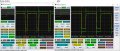
I changed the black (mosfet 1) and the blue (mosfet 2) drain wires to the coils. Apparently drain signals do not change; I guess I can conclude the coils are not the cause of not starting. How to debug furtheron?
Hello, I would like to repair this brushless 12V fridge compressor motor (Danfoss 2.5) but first of all understand how it functions.
Inside are 3 coils.
It has an electronic driving unit: 2coils (photo 3)pin1-pin3 and pin3-pin4 of them are driven by mosfets. Total number of mosfets=3:
(the third one is for the fan). There is no mosfet driving the coil between connectorpin 2 and 3 ("WT" on PCB). View attachment 220693I add a diagram (temptative). View attachment 220694 View attachment 220692
I have the same unit - with a noddy problem. I need (external) wiring connections between the Danfoss unit (illustated 102N3033) and the connector block (illustrated). I planned to replace the compressor unit case (dissolved - rusted - in a boat) and disconnected these cables. I took a photo, fell off the ladder and smasshed the 'phone. I hope you can help.
I have similar equipment, offering refrigeration on a boat. The unit ( and boat) are old and the steel case, which was hidden away, was found to be corroded and in pieces, which were funally spilling out. Owing to other work, the unit has been unused for a period.
A problem (incidentally) about a replacement compressor, is connections and re-gassing.
Your photos seem to show an integrated cable (to the compressor) connected into the control unit (102N3033).
Mine simply has an array of spade (fast-on?) tabs.
I have lost the photo showing the four connections from the compressor which I dismantled in accessing the metal case: my problem now is, which wire went to what terminal on 102 N3033.
There are options shown in other posts for other accessories: a fan (terminals C&F) and an LED.
I assume that a (separate) on/off switch unit on the boat (with monitoring circuitry) is fed by T & C. That unit poses other dilemmas.
A fan was included in the broken compressor case, but not wired in.
I hope you can advise where the four cables were conected.


 Facebook
 Google
 GitHub
 Linkedin