Facebook
 Google
 GitHub
 Linkedin
Hello forum!
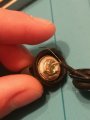
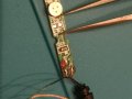
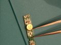
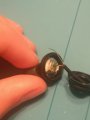
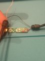
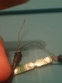
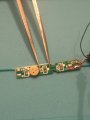
My sibling broke their earphones and I am trying to repair them, but cannot understand on which solder pad should I solder the "golden" wire, because the pads are identical to me. I looked for schematic online, but could not find one and since these are fake I guess there won't be an accurate one. The earphones were ripped from the microphone area. There are two ripped wires - one blue and one golden. Because the speaker needs two wires I suppose the blue one was the missing one from the speaker (there was one wire ripped from the speaker area too) , because the golden was still on the speaker. The golden wire is on the speaker but ripped from the microphone's pcb. I see two solder pads on the pcb and they look identical. My question is which of the pads should the golden wire go to? I Will be very thankful for any help!
My sibling broke their earphones and I am trying to repair them, but cannot understand on which solder pad should I solder the "golden" wire, because the pads are identical to me. I looked for schematic online, but could not find one and since these are fake I guess there won't be an accurate one. The earphones were ripped from the microphone area. There are two ripped wires - one blue and one golden. Because the speaker needs two wires I suppose the blue one was the missing one from the speaker (there was one wire ripped from the speaker area too) , because the golden was still on the speaker. The golden wire is on the speaker but ripped from the microphone's pcb. I see two solder pads on the pcb and they look identical. My question is which of the pads should the golden wire go to? I Will be very thankful for any help!
Attachments
-
 1.7 MB Views: 12
 -
 3.2 MB Views: 12
 -
 3.3 MB Views: 11
 -
 3.1 MB Views: 9