Can I use a single 2N3904 with three LEDs? +Simulation Issue

Thread Starter

LiverDye

Joined Oct 26, 2016
9
Hello everyone, thank you for taking the time to look at my problem. I want to make a lamp that will have "pulsing" LEDs (red,green, and blue) that can be turned on individually to create different colors, as well as just having a constant on/non-pulsing state. First I made a simulation with one LED -- and it worked just as I expected it to, Figure 1 (I sourced this circuit from an instructable).

fadingledcircuit_555timer.PNG
Figure 1: Circuit version 1

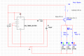
Now here's where I have some questions: naturally I thought of just connecting two more LED's in parallel with a 3-DIP switch in between the transistor and LEDs, Figure 2.

The result would be that in the pulsing state I could create multiple colors combining the red, green and blue LEDs. Is it bad practice to connect the LEDs to one transistor? Should I use three separate transistors? Currently I don't think there is an issue with the amount of current being drawn from the single emitter branch to "fuel" all three LEDs, but I'm not 100% sure.

errenous_ckt.PNG

Figure 2: Initial circuit for second revision with issues,

Also, in my simulation for Figure 2, sometimes the transistor's collector current fluctuates between 200 pico amps to 1 nA -- even if I switch the LEDs on, individually or multiple-ly(sp?). I also check the simulation time and switched it to "fast as possible" but to no avail :( So in other words, it doesn't work at all. (but sometimes it does, ugh!!!)

I greatly appreciate a fresh set of eyes and some knowledge. Thank you!!
 

MrChips

Joined Oct 2, 2009
30,707
That is bad practice.

Firstly, your LEDs are placed on the emitter of the transistor.
It is better to put the LED on the collector leg of the transistor. This way, a 1V input on the base of the transistor will turn on the LEDs.

Secondly, LEDs, particularly of different colors have different TURN-ON voltages.
By connecting the LEDs in parallel, some LEDs will be brighter than others.

I see you have current limiting resistors for each LED. This is appropriate.
Use the 470Ω resistor on each LED, regardless of the number of LEDs you connect to the single transistor's collector.

You may want to look at this:
http://forum.allaboutcircuits.com/threads/leds-555s-flashers-and-light-chasers.19075/
 

AlbertHall

Joined Jun 4, 2014
12,345
It is better to put the LED on the collector leg of the transistor. This way, a 1V input on the base of the transistor will turn on the LEDs.
The circuit shown won't 'flash' the LEDs as they are fed with a sawtooth waveform they will fade in and out. If that is the intended effect then putting them in the collector won't work.
 

Thread Starter

LiverDye

Joined Oct 26, 2016
9
The circuit shown won't 'flash' the LEDs as they are fed with a sawtooth waveform they will fade in and out. If that is the intended effect then putting them in the collector won't work.
The goal of my project is to have them fading, not flashing. Just to clarify, you are saying that if I place them in the collector branch, they will flash on-off?

thanks!
 

Thread Starter

LiverDye

Joined Oct 26, 2016
9
What is the purpose of S1 and R3? :confused:
The purpose of the switch is so that the user can have the lamp either "glowing" (state 1) or constantly on (state 2). I have since re-arranged my circuit, so that the switch is connected directly to the +9 volts instead of the 555 timer's output.
 

Thread Starter

LiverDye

Joined Oct 26, 2016
9
You need to decrease R2 and increase C1, i.e. make R2 1kΩ and C2 1000μF.

Thanks I will try that. I was running into issues with my capacitor not discharging. Once I get a screenshot of my updated circuit diagram I will post it. I checked my connections, because I thought maybe I was missing a branch to allow the capacitor to discharge, but to no avail. Thanks again for your tip.
 

Thread Starter

LiverDye

Joined Oct 26, 2016
9
Hey guys! So I fixed my circuit (as seen below) but then I was running into a new issue. When my circuit reached this state (I've included the probe values) the simulation would shut off, saying that there has been a "convergence issue". Now I had an inkling feeling that it had something to do with the DIP switch....


fadingled_error.PNG


....and my inkling was right! I replaced the DIP switch with regular switches (Figure 4.1, 4.2) and my circuit works perfectly.

upload_2016-11-1_10-23-12.png
Figure 4.1: Fading LEDS

upload_2016-11-1_10-23-47.png
Figure 4.2: Constant on LEDs


(I forgot to change one of the LEDs to blue)
 

Attachments

AnalogKid

Joined Aug 1, 2013
10,986
Not quite there yet. The problem with your S4 arrangement is that in the lower schematic, it places a constant 9 V on the emitter while the base ramps between 9 V and 3 V. This places -6 V across the base-emitter junction, which is rated for only -5 V.

Connect the S4 common terminal to the line sourcing the three LEDs.
Connect one throw to the Q1 emitter.
Connect the other throw to +9 V.

In this way, the emitter is floating when the circuit is in the 'constant ON' mode. This is ok.

ak
 

Thread Starter

LiverDye

Joined Oct 26, 2016
9
Not quite there yet. The problem with your S4 arrangement is that in the lower schematic, it places a constant 9 V on the emitter while the base ramps between 9 V and 3 V. This places -6 V across the base-emitter junction, which is rated for only -5 V.

Connect the S4 common terminal to the line sourcing the three LEDs.
Connect one throw to the Q1 emitter.
Connect the other throw to +9 V.

In this way, the emitter is floating when the circuit is in the 'constant ON' mode. This is ok.

ak
Doh, didn't even think of that - thank you for pointing that out. That sucker would have been hot and dysfunctional as a bagel bite.

If I understood your directions correctly, I've reconnected it like so:
upload_2016-11-1_11-15-57.png
 
Top