Can I better stabilize HX711 output with load cell?

Thread Starter

ballsystemlord

Joined Nov 19, 2018
253
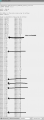
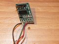
Sorry for taking so long. Here's the picture.
I've also measured the resistances on an unloaded scale (please note that it's approximate as my table isn't perfectly flat).

BKE+WHE-401ohms
BKE+GrA-288.2ohms
BKE+RdA+288.2ohms
WhE-GrA-288.6ohms
WhE-RdA+288.6ohms
GrA-RdA+351.3ohms

I've also read through the Loadapp.pdf file. It's very informative. It seems to me that my ohms readings are within tolerance. I didn't look into the mV/V but I could if you wanted me to.
EDIT: Not because I am lazy, but because I'm uncertain how to feed the scale one voltage while ensuring the hx711 gets another, lower voltage.
 

Attachments

Last edited:

ericgibbs

Joined Jan 29, 2010
21,487
hi bal,
Downloaded your L/C resistance values, will check out the information and post the results.

Note: when powering on the Sketch and L/C, you should have the scale pan [if it has one] in place on the scale so that the weight of the pan is 'Tared Off'.

You are showing an Offset of +35gm at the supposed Calibration point in the results table.?

Do you have a photo of the project, so that we can see the wiring details?
You seem to have a lot of 'electrical noise' on the weight results.

Have you confirmed that you have just under +5V on the +/-E lines.?

E
 

Thread Starter

ballsystemlord

Joined Nov 19, 2018
253
Currently, I don't have the scale attached to it's base.
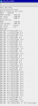
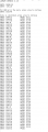
Here's the output of your program. I placed a 100gram calibration weight onto the scale. As you can see, the result is totally wrong.
Also, I know my solder joints aren't too pretty. They were better before, but after re-doing the soldering 5 times, I decided it wasn't worth making it perfect until I got a working setup.
IDK if it makes a difference, but I'm using the digital pins whereas your code is using the analog ones. I have no idea why.

I de-soldered the black wire (E+) and measured the voltage. It's at 4.156v. Considering I should be feeding the scale 5v minimum, I'm wondering if that's part of my problem. I never imagined I'd loose 850mv across the USB connection to the scale. I could boost the voltage, using an independent source, to 5.5v at the HX711.
 

Attachments

Last edited:

ericgibbs

Joined Jan 29, 2010
21,487
hi bal,
Did you carefully read the ino file I posted.

Clip:
/ by the SCALE parameter (not set yet)
// this value is obtained by calibrating the scale with known weights;

scale.set_scale(146.73); // EDIT to suit the LOAD CELL being used

scale.tare();// reset the scale to 0.0
Serial.println("Scale not Set:");
........

Currently, I don't have the scale attached to it's base.
It will never work reliably used in that way, as shown in the photo
It needs to be bolted down to a firm metal Base plate, add a couple of metal washers between the LC and Base, so the L/C so that the L/C can flex.

Here's the output of your program. I placed a 100gram calibration weight onto the scale.
As you can see, the result is totally wrong.

It is not wrong, you have not set the Calibration constant correctly, ref above ino.

Also, I know my solder joints aren't too pretty. They were better before, but after re-doing the soldering 5 times, I decided it wasn't worth making it perfect until I got a working setup.
It is a bad idea to try to debug and test a project that is not assembled as well as possible.

IDK if it makes a difference, but I'm using the digital pins whereas your code is using the analogue ones. I have no idea why.
The choice of pins in Analogue makes no difference at all in the program's performance.

I de-soldered the black wire (E+) and measured the voltage. It's at 4.156v. Considering I should be feeding the scale 5v minimum, I'm wondering if that's part of my problem.
The HX711 is a ratio metric ADC, which means the voltage supply to the HX711's internal ADC and the Load Cell must be the same voltage. A voltage of +4.156v is not a problem.

I never imagined I'd loose 850mv across the USB connection to the scale.
I could boost the voltage, using an independent source, to 5.5v at the HX711.

A USB voltage source can be slightly lower than +5V

Sorry I sound blunt, but unless you fix the L/C assemble to a suitable Base plate, you will not get the test results you expect.

On the Calibration.
scale.set_scale(146.73); // EDIT to suit the LOAD CELL being used
As your L/C is 200kG and mine is only 30kG, an initial 'guess' value 146.73 * ( 30/200) =21.9

1. scale.set_scale(21.9);
2. With No load on the cell, run the Sketch, it should display close to 0gm
3. Place the 100gm test weight on the cell, it should Read to 100gm
4. Note any difference between the target of 100gm and the actual shown value.
5. Remove the 100gm weight
6. IF there is a big error difference in the displayed value and 100gm, go back to beginning of this calibration sequence, ie #1
7. then you need to calibrate using a test weight Close to the weights you expect when actually using the scale


Footnote:
Your posted nominal 15gm reading for a 100gm actual weight.
Your 200kg L/C and My 30kg L/C, Ratio of 200/30 = 6.66
So 15gm * 6.66 = 100gm.
 
Last edited:

Thread Starter

ballsystemlord

Joined Nov 19, 2018
253
This is just a bit of an update, since the M7 bolts I got don't fit the scale. I'm really uncertain what size the bolt holes are. They're 6.64mm internal diameter +/- 0.01mm. Maybe they're M7.5? That would be weird though. I'll try M8 next -- but it didn't seem that such a large bolt would fit.

hi bal,
Did you carefully read the ino file I posted.
No.
As someone who's gone as far as debugging the Linux kernel, I learned to trust that the person handing me the code would tell me if it needed adjustment.
Apparently, it's different for the arduino. I'll be more aware.

Also, I know my solder joints aren't too pretty. They were better before, but after re-doing the soldering 5 times, I decided it wasn't worth making it perfect until I got a working setup.
It is a bad idea to try to debug and test a project that is not assembled as well as possible.
Considering I found the problem when I had nice joints before, I think you're exaggerating the severity of the problem -- but then I'm the one who's complaining about a 50g fluctuation on a 200kg scale. I fixed the joints and cleaned them. They're in perfect condition. The problem persists.

Sorry I sound blunt, but unless you fix the L/C assemble to a suitable Base plate, you will not get the test results you expect.
Blunt is a good thing to be. I'm very blunt. The shortest distance between any 2 points is a straight line. No need to "beat around the bush".
Everything else in my life I've heard about you.
1: Research what you want.
2: Get it.
3: Qualify it.
4: Install it.
5: Verify that it works once installed.

What makes load cells different in this regard?
 

ericgibbs

Joined Jan 29, 2010
21,487
What makes load cells different in this regard?
hi bal,
If you want to calibrate a 200kG, you should use at least a calibrated test weight of 100kG, ideally 200kG.

A fluctuation of +/-50gm on a 200kG scale weighing system, I would not consider as a problem

The load cell must be bolted to a solid metal Base plate.

The signal levels from a Load cell are down in the microvolt's region, and care is required in its construction when used in a weighing system. I have been commercially working with L/C's since around 1964.

It is unfortunate you think I am 'exaggerating the severity of the problem'.
Perhaps someone else will post to help with your project.

E
 

drjohsmith

Joined Dec 13, 2021
1,622
This is just a bit of an update, since the M7 bolts I got don't fit the scale. I'm really uncertain what size the bolt holes are. They're 6.64mm internal diameter +/- 0.01mm. Maybe they're M7.5? That would be weird though. I'll try M8 next -- but it didn't seem that such a large bolt would fit.


No.
As someone who's gone as far as debugging the Linux kernel, I learned to trust that the person handing me the code would tell me if it needed adjustment.
Apparently, it's different for the arduino. I'll be more aware.


Considering I found the problem when I had nice joints before, I think you're exaggerating the severity of the problem -- but then I'm the one who's complaining about a 50g fluctuation on a 200kg scale. I fixed the joints and cleaned them. They're in perfect condition. The problem persists.


Blunt is a good thing to be. I'm very blunt. The shortest distance between any 2 points is a straight line. No need to "beat around the bush".
Everything else in my life I've heard about you.
1: Research what you want.
2: Get it.
3: Qualify it.
4: Install it.
5: Verify that it works once installed.

What makes load cells different in this regard?
HI @ballsystemlord

You say blunt is a good thing
please remember that we all give our time and experience for free on the forums
Blunt does not always go down well.

you say
"As someone who's gone as far as debugging the Linux kernel, I learned to trust that the person handing me the code would tell me if it needed adjustment. Apparently, it's different for the arduino. I'll be more aware."

Linux Kernel code is used by millions, and is very very different to hobbyist code for a micro controller.
Code given as a demo, is given as is , its up to the user to read and understand the code,

I think you misunderstand the comment about the joints,
When I de bug, I like to have a few variables as possible,
it makes localising the cause much easer
Bad joins have definite capability of causing problems
and its easy to do a good joint,
so the suggestion is that its adding potential problems by having known bad joints.

Your into the 80:20 rule of measurements
its easy to get something 80 % of the way, but to get the last 20 percent of the accuracy / resolution
gets increasingly harder

As has been mentioned
the basics need to be right
this is a mechanical thing that has to be right before the s/w
The Load Cell needs to be mounted securely / low vibration
The circuit needs to be of "good quality" and reliable
Analog circuitry and thermals need to be considered / designed correct.

Most of a scales design is mechanical, then electrical , and the easy bit is the code.
 

Thread Starter

ballsystemlord

Joined Nov 19, 2018
253
hi bal,
If you want to calibrate a 200kG, you should use at least a calibrated test weight of 100kG, ideally 200kG.

A fluctuation of +/-50gm on a 200kG scale weighing system, I would not consider as a problem

The load cell must be bolted to a solid metal Base plate.
I'm glad you told me. I was thinking of using a sturdy 2x4 wood base.
I thought a lot about the load. I can create a 200kg load. But it will have to be in 5kg increments as that's the max weight of the next scale down that I have. It's accuracy will be +/- 40g. Would that work, or do you have another idea maybe?

The signal levels from a Load cell are down in the microvolt's region, and care is required in its construction when used in a weighing system. I have been commercially working with L/C's since around 1964.
Amazing!

It is unfortunate you think I am 'exaggerating the severity of the problem'.
Perhaps someone else will post to help with your project.
Ok, that was unexpected. I reasoned you'd agree or disagree (in which case I'd learn why in the process (Thanks @drjohsmith )). I did redo the joints.
The reason I chose to say that was because I find electronics all the time that I purchase that have much higher signalling rates and have joints that either were not done correctly (if at all), or were never cleaned. Hence, I asked myself if it really made a difference to make mine clean as I didn't know if I'd have to rework the board again and I said "No".

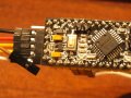
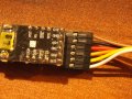
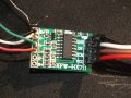
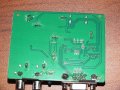
Here's a picture of my new joints and a recent shot of an HDMI to VGA adapter I purchased. It's $25 -- not a cheap adapter comparative to others like it.

Mind, the above was not an attempt as disregarding you (or whatever). I'm just explaining where I'm coming from in hopes that we'll better understand each other when we're being blunt.
 

Attachments

Thread Starter

ballsystemlord

Joined Nov 19, 2018
253
Addendum: I really didn't think I'd need anything nearly as heavy as 200kg to calibrate the scale with. That's why I don't have anything prepared.
 

drjohsmith

Joined Dec 13, 2021
1,622
Addendum: I really didn't think I'd need anything nearly as heavy as 200kg to calibrate the scale with. That's why I don't have anything prepared.
Well done for doing the joints again .
It only adds potential problems not getting the basics right.

Re the 200 Kg .
Are these strain gauges linear ?
I've used ones in past that need a calibration curve not a straight line.

50g in 200Kg is a hard mechanical job, don't under estimate it .
 

Thread Starter

ballsystemlord

Joined Nov 19, 2018
253
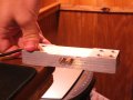
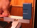
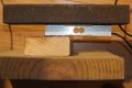
I made it a steel base. Figuring out the correct bolt sizes took some time. All boltholes are populated. I'm using 2 regular steel washers per screw to hold the scale off the base and top.
It looks to be a bit more stable than before when it has weight on it.

I also used your code @ericgibbs . I adjusted the value for tar-ing the scale to 21, which seems about right. If there's something else about my setup you'd like to see improved, feel free to mention it.


Any further suggestions would be helpful.

Thanks!
 

Attachments

Top