 Facebook
 Google
 GitHub
 Linkedin
Hi,
Having searched and searched I'm really stumped - I'm restoring a 1970s Smith car clock and while I know a little electronics I'm still very much a beginner so really could do with some help.
From what I can work out the clock uses a simple oscillator circuit (transistor, 3 resistors a capacitor) to oscillate a coil's magnetic field... Which then mechanically makes everything tick. However there's not enough power being sent to the coil at present to get any 'ticks'. So after checking for dry joints/breaks, I thought I'd replace what I assume is the capacitor (which must be 50 years old).
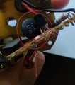
So I opened the clock up and found this in the attached photo - what looks like a capacitor, but with 47nZ written on it, rather than say 47nF - I'm now really doubting myself as I thought Z was for impedance - What's going on?
Thanks hugely for any help in this
Having searched and searched I'm really stumped - I'm restoring a 1970s Smith car clock and while I know a little electronics I'm still very much a beginner so really could do with some help.
From what I can work out the clock uses a simple oscillator circuit (transistor, 3 resistors a capacitor) to oscillate a coil's magnetic field... Which then mechanically makes everything tick. However there's not enough power being sent to the coil at present to get any 'ticks'. So after checking for dry joints/breaks, I thought I'd replace what I assume is the capacitor (which must be 50 years old).
So I opened the clock up and found this in the attached photo - what looks like a capacitor, but with 47nZ written on it, rather than say 47nF - I'm now really doubting myself as I thought Z was for impedance - What's going on?
Thanks hugely for any help in this
Attachments
-
 323.6 KB Views: 46


