If You see on the datasheet of both transistors, they have 2x built-in 47k biasing resistors the model of LTspice has not inserted, so I added them manually externally
You know what?
I was thinking since this driver (PCB) comes built by a small italian company that sells LED, maybe:
1. the designer was simply wrong, and made a mistake he even figured out he made.
2.OR please see below.
THOUGHT 1:
I mean, please follow me
They sell this small drivers to steer 100% PWM the LED. Thay have on their catalogue same design with 4 different Rsense to accomplish different output currents, but that's it.
If it's written on the datasheet that leaving pin2 unconnected it pulls internally the pin high to 100% PWM. So why add extra stuff?? but maybe he did pass by this datasheet info. And he wanted to keep pin2 at 2,5V level without the result.
I have seen, simulated, and measured that Q2 is OFF, so no current is drawn out the collector. NO way to discuss.
Q2 in this state is unable to pull away pin2 from his HIGH state, so PWM is 100%.
Maybe really the simplest solution is that we are trying to figure out something from a mistake.
OR...
SOLUTION #2
Look what happens if I leave unconnected pin2 on the simulation:
there is a small voltage drift.
Maybe keeping the Q2 connected does stabilize at fixed internal reference voltage all the circuit...
who knows.
Not specifically -- No. There is a general problem with providing the information needed to solve problems. The most egregious cases are the ones with a verbal description of a circuit with no schematic diagram in sight. At least you made an effort to help us help you.
If You see on the datasheet of both transistors, they have 2x built-in 47k biasing resistors the model of LTspice has not inserted, so I added them manually externally
You know what?
I was thinking since this driver (PCB) comes built by a small italian company that sells LED, maybe:
1. the designer was simply wrong, and made a mistake he even figured out he made.
2.OR please see below.
THOUGHT 1:
I mean, please follow me
They sell this small drivers to steer 100% PWM the LED. Thay have on their catalogue same design with 4 different Rsense to accomplish different output currents, but that's it.
If it's written on the datasheet that leaving pin2 unconnected it pulls internally the pin high to 100% PWM. So why add extra stuff?? but maybe he did pass by this datasheet info. And he wanted to keep pin2 at 2,5V level without the result.
I have seen, simulated, and measured that Q2 is OFF, so no current is drawn out the collector. NO way to discuss. View attachment 329617
Q2 in this state is unable to pull away pin2 from his HIGH state, so PWM is 100%.
Maybe really the simplest solution is that we are trying to figure out something from a mistake.
OR...
SOLUTION #2
Look what happens if I leave unconnected pin2 on the simulation:
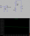
there is a small voltage drift. View attachment 329624
Maybe keeping the Q2 connected does stabilize at fixed internal reference voltage all the circuit...
who knows.
I think that people who go to the trouble to make printed circuit boards have a good idea of what they are trying to do and if the cost of fabrication and assembly is coming out of their pocket, I think a great deal of care was exercised in the development and testing of this circuit. Just because we are unable to divine their intentions and thought processes is not an indictment of their work.

 Facebook
 Google
 GitHub
 Linkedin