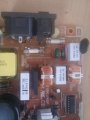
And what resistance do you read out of circuit?I have tested it out of circuit.
I think you might be right thanks.It may be an inductor, especially if the housing is polished. If the housing looks ceramic, it is most probably a power resistor.
The colors are quite off in your photograph. It could be...
Purple - 7
Green - 5
Yellow (?) - 4
Gold (?) - x0.1
Brown (?) - 1% tolerance
That would make a 75Ω resistor
Or:
Brown (?) - 1
Orange (?) - 3
Yellow (?) - 4
Green - x10000
Purple - 0.1% tolerance
That would make a 1.34MΩ
http://www.resistorguide.com/resistor-values/
https://www.electronics-tutorials.ws/resistor/res_2.html
I get 0 resistance or else I'm doing something wrong.And what resistance do you read out of circuit?
Terms:I get 0 resistance or else I'm doing something wrong.
My multimeter shows 1 when I switch it to Ohm values. When I measure the component off cI get 1 as well. When I measure any other resistor off circuit I get a reading.So you get the same reading across this component as when you touch the two meter leads together?
And a different reading when the leads are not connected to anything, perhaps 0L?
I will do just that thanksAs you have the schematic why not post it so that forum members can see if there is anything connected to the resistor that will cause an incorrect reading when measuring it in circuit. It's location in the schematic will also give an idea of the likely value.
Les.
Does this all apply to the 20M range as well?My multimeter shows 1 when I switch it to Ohm values. When I measure the component off cI get 1 as well. When I measure any other resistor off circuit I get a reading.
So it is a mains voltage rated 750k resistor whose purpose is to discharge the interference supression capacitors on the mains input to prevent the user getting a shock when unplugged.Here is the schematic and the power supply itself. I assume the resistor is the one I highlighted on the schematic.
by Aaron Carman
by Duane Benson
by Jake Hertz
by Duane Benson