Can a reflector be used with an 11 meter dipole antenna to boost performance?

LowQCab

Joined Nov 6, 2012
5,102
Kinda humorous that the guy in the Attic Article quoted above
was so meticulous about removing the exact same number of turns from BOTH Antennas
when the "Ground Plane" Antenna is somewhere around ~3.5" longer than
the Main Radiator because of that substantial steel Mounting Bracket that he fabricated.

He could have also picked-up ~3 to 5db of Gain by creating a proper 45 degree Ground Plane
using plain Copper Wires, ( at least 3 of them, and more is always better),
that are at least 9+ feet long,
attached to his nice steel Bracket,
and then spread-out across the Attic,
and secured with a nail to any convenient Ceiling Rafter.
This will work perfectly well,
there is no need for the Ground Plain, ( or "counter poise" element ),
to be an exact mirror image of the Main Driven Element.
But it is very important that it is effectively 9+ feet long, so as to resonate well with the Driven Element.

Ground Planes are very interesting in that,
as long as the Radials are at least 1/4 Wavelength long, or more,
and there are at least 3 of them,
then the exact length of the Radials will have little effect on SWR,
but can have a very large effect on Radiation Pattern, and overall Antenna Radiating Efficiency.
These effects improve all the way up to 3 Wavelengths in Radius, away from the Driven Element,
but past 3 Wavelengths, there is very little measurable improvement .

Using a Loaded Main Radiator may be necessary when space is limited,
but it causes the Radiation Pattern to be much higher than is desirable for Local Communication use,
which needs to be as low and flat to the Horizon as possible,
but instead, tends to substantially favor Skip communication.

The solution to this is to create a "Bi-Cone" Antenna, where there are multiple Radiators arranged
in a mirror image of the 45 degree Ground Plane Radials.
This type of Antenna has excellent Gain, and typically very low SWRs, over a broad band of frequencies,
and high immunity to Atmospheric Noise which plagues most Vertically Polarized Antennas,
and are generally described as a "Broad-Band" Antenna.

The Impedance of a Bi-Cone Antenna is directly related to the Included Angle between
the Driven Elements, and the Ground Plane Elements.
90 degrees results in roughly ~30 Ohms,
135 degrees results in roughly ~50 Ohms,
and 180 degrees is a Di-Pole Antenna, which has Roughly ~75 Ohms Impedance.
The SWR will, of course, be the lowest at ~50 Ohms,
but this may not provide the best possible performance from this Antenna,
as the Gain increases substantially, (as much as ~6db), as the Included Angle approaches 90 degrees,
and has an extremely FLAT Radiation Pattern,
achieving the best Omni-Directional Pattern possible for Local Communications.
.
.
 

Thread Starter

Darkstar

Joined Sep 3, 2010
182
Kinda humorous that the guy in the Attic Article quoted above
was so meticulous about removing the exact same number of turns from BOTH Antennas
when the "Ground Plane" Antenna is somewhere around ~3.5" longer than
the Main Radiator because of that substantial steel Mounting Bracket that he fabricated.

He could have also picked-up ~3 to 5db of Gain by creating a proper 45 degree Ground Plane
using plain Copper Wires, ( at least 3 of them, and more is always better),
that are at least 9+ feet long,
attached to his nice steel Bracket,
and then spread-out across the Attic,
and secured with a nail to any convenient Ceiling Rafter.
This will work perfectly well,
there is no need for the Ground Plain, ( or "counter poise" element ),
to be an exact mirror image of the Main Driven Element.
But it is very important that it is effectively 9+ feet long, so as to resonate well with the Driven Element.

Ground Planes are very interesting in that,
as long as the Radials are at least 1/4 Wavelength long, or more,
and there are at least 3 of them,
then the exact length of the Radials will have little effect on SWR,
but can have a very large effect on Radiation Pattern, and overall Antenna Radiating Efficiency.
These effects improve all the way up to 3 Wavelengths in Radius, away from the Driven Element,
but past 3 Wavelengths, there is very little measurable improvement .

Using a Loaded Main Radiator may be necessary when space is limited,
but it causes the Radiation Pattern to be much higher than is desirable for Local Communication use,
which needs to be as low and flat to the Horizon as possible,
but instead, tends to substantially favor Skip communication.

The solution to this is to create a "Bi-Cone" Antenna, where there are multiple Radiators arranged
in a mirror image of the 45 degree Ground Plane Radials.
This type of Antenna has excellent Gain, and typically very low SWRs, over a broad band of frequencies,
and high immunity to Atmospheric Noise which plagues most Vertically Polarized Antennas,
and are generally described as a "Broad-Band" Antenna.

The Impedance of a Bi-Cone Antenna is directly related to the Included Angle between
the Driven Elements, and the Ground Plane Elements.
90 degrees results in roughly ~30 Ohms,
135 degrees results in roughly ~50 Ohms,
and 180 degrees is a Di-Pole Antenna, which has Roughly ~75 Ohms Impedance.
The SWR will, of course, be the lowest at ~50 Ohms,
but this may not provide the best possible performance from this Antenna,
as the Gain increases substantially, (as much as ~6db), as the Included Angle approaches 90 degrees,
and has an extremely FLAT Radiation Pattern,
achieving the best Omni-Directional Pattern possible for Local Communications.
.
.
I tried to put the 18' half wave in the attic back in the 70's and had to bend the top 1.5' at 90* for it to fit under the roof peak. I have quite a bit of 1/4'' copper tubing so I was thinking I should be able to fit a 103'' vertical and 3 or 4 103'' ground planes. The half wave I used to have on my roof in the 60's had 90* radials and my tuner was able to match it just fine. If I had to I think I should be able to have the radials at anywhere between 45* and 90* in the attic, even if I have to use more than one angle to make them fit.

Here's something I found back in the 70's as I was trying to use any kind of antenna I could fit indoors. Their SWR was sometimes far from 50 ohms. I had 2 antenna tuners so I tried using them together for greater tuning range and it worked. I might be able to get down to SWR of 3 using one tuner but with both I can get all the way to 1.0. They can be connected directly or with a short patch cable at either the radio or ant side of the main cable. The only thing you can't do is use one at each end. As I recall, the SWR may read low but little signal is radiated. I figured it set up a resonant section of coax and most of the signal stayed in there. I still sometimes use that combination. I had to use it with the mobile ant on the metal picnic table ground plane.

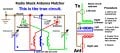
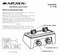
These ant tuners were bought at Radio Shack when I got the big antenna. They have a strange wiring which does not seem to make sense. Inside are 3 air coils wrapped as one and 2 trimmer caps. When checking continuity, notice how the red circuit has the center conductor shorted to gnd and the blue circuit has the left trimmer shorted. I finally unsoldered the wires to see how they were wired. I attached a diagram. It's not wired wrong, both are exactly the same. I've never seen this wiring scheme in any published tuner schematic, but it works. I've always connected the radio on the left and ant on the right but for some reason with the dipole I'm using now I can't get below 2:1 unless I reverse the connections, then 1.0:1 is easy. The dipole works with either 1 or 2 tuners. Radio Shack Antenna Matcher, Redrawn 1.jpgRadio Shack Matcher Pkg.jpg
 

LowQCab

Joined Nov 6, 2012
5,102
OK, I'm going to step on somebody's toes here ...........

STOP WORSHIPING THE "GOD OF SWR".
SWR is only ONE, easy to measure, "Indicator".
It is NOT the "End-All-Be-All" "Holy-Grail" of Antenna function.
You can throw an odd piece of wire out of your window,
and then "Tune" it with a Match-Box, or what ever,
and finally wind up with a 1.1:1 SWR .
THAT DOES NOT MEAN IT WILL TRANSMIT OR RECEIVE WELL !!!!!!
It will have low Radiating Efficiency.
(and generally speaking, anything that improves Radiating Efficiency, also improves Reception to a degree )
You can also have 75 feet of cheap skinny Coax, and loose fully half your power, and still have a "perfect" SWR.
The same goes for many "compact" Antenna designs,
some of which are almost equal to a Dummy-Load,
but they can deliver an almost "perfect" SWR.
Then there are the Antennas that may "look" impressive, but radiate 75% of their Power into the Sky,
still with a "perfect" SWR.

You need to make sure that your Antenna has a Radiation Pattern
that puts the vast majority of your Signal where you want it,
which is generally down tight to the Horizon, with the Antenna as high off the ground as you can get it.
There's nothing to be gained by sending your signal into Outer-Space, (unless you're into "Skip").
So, the choices are, (in order of effectiveness) .......

Omni Directional :

Co-Linear Vertical Array,
( not practical at all on 11-Meters ),
(Huge, Really Tall, and Extremely Efficient),
( Perfect Radiation Pattern = Squashed Donut ),
( VERY Low Reception Noise ),

Bi-Cone,
( ~9 feet tall and ~20 feet in diameter ),
( can be made physically larger with great improvements ),
( Excellent Flat Radiation Pattern ),
( VERY Low Reception Noise ),

5/8 Wave Vertical Ground Plane,
( 3/4 Wavelength Radiator w/ tip folded back to create 5/8 WL dimension ),
(~22 feet tall and ~15 feet in Diameter Ground Plane ),
( Very Good "Cylindrical" Radiation Pattern ),
( Bullet-Proof Stability and SWR Levels because of 3/4 Wavelength )

1/4 Wave Vertical Ground Plane,
(~9 feet tall, ~15 feet in diameter Ground Plane),
( High Radiation Pattern),
( Noisy Reception ),

1/8th Wave Vertical with Continuously-Loaded Fiber Glass Elements,
( 6 feet X 6 feet of space),
( Virtually Spherical Radiation Pattern ),
( VERY Noisy Reception ),
Smallest form factor possible for reasonable performance on 11-Meters / 27-Mhz.
( Bullet-Proof Stability and SWR Levels because of Continuously Loaded Elements ).
( Low Gain ),

Directional Antennas,

4-Element Vertical Phased Array, Horizontally Spaced on a Common Support, on a dedicated Mast,
Takes up HUGE Space, but is an Excellent design for Vertically Polarized Reception Quality.
( VERY Low Noise Reception, because of 4 Driven Elements )
( Narrow Figure-8 Radiation Pattern ),
( ~36 feet wide, ~18 feet tall, requires substantial structural support ).

Side-Fed, 4-Element, Quad Beam,
Doable, if you have plenty of space and a dedicated Antenna Mast.
Excellent Gain,
( VERY Low Noise Reception because of "Full-Wave-Loop" design )

4-Element Vertical Yagi, almost as good as Quad-Beam above, but takes up more Vertical Space.
( can be Noisy because of only one, "Open-Ended" Driven-Element ),

A very rudimentary Directional Array can be made by using a quantity of 2 or 4 of the above described
"1/8th Wave Vertical with Continuously-Loaded Fiber Glass Elements" Antennas,
with proper 1/4 WL Spacing between Antennas and calculated Coax Phasing,
this setup can provide 2- Switchable, "Figure-8" Radiation Patterns, that are 90 degrees apart.
( Cheap and Portable, can be set up anywhere, even in an empty Grass Field ),
( as much, or slightly more Gain than full sized 1/4 WL Vertical,
( Fair Rejection of Side Signals ),
( Fair Reception Noise Rejection ),
( Wide Figure-8 Radiation Pattern )
( Self-Supporting, No Mast Required ).


There is an old saying that goes something like ........
To build a good Antenna, you have to put lots of Metal up in the Air
( I am probably mis-quoting this, but it's close )
Well, this is partially true ........
Small Antennas, (relative to the dimension of one Quarter Wavelength),
will always have poor Efficiency, and be difficult to tune, when compared to a "full-sized" Antenna.

Any time you have to "add-on" a tuning device, you can rest assured that YOU DID SOMETHING WRONG.
ANY type of Antenna Tuning Technique is just some one's weird solution to getting
20-pounds of crap into a 5-pound bag.
This is SO common with Hams that it just seems to be SOP (standard operating procedure),
because they historically were working with the lower frequencies,
which require MASSIVE Antennas to work at any kind of reasonable efficiency level.

CB Radio is in the position where a Quarter Wavelength is usually a manageable size, but still fairly large,
AND A QUARTER WAVELENGTH ANTENNA WILL "RESONATE".
Smaller than 1/4 WL Antennas must be "tricked" into resonating with add-on devices.
A 1/4 WL can Resonate whether it has a 20 Ohm Impedance, or a 450 Ohm Impedance.
It can Resonate with an SWR of 9:1.
How strongly it resonates depends upon GEOMETRY and the behavior of Electromagnetic Waves.
If it Resonates, it "might be" a good Antenna.
If it can't Resonate, it's probably not a very good Antenna, (but there are some exceptions to this rule).
SWR does NOT indicate that the Antenna is Resonating well, or Radiating any Power.
SWR just indicates whether or not a properly designed Antenna is
"playing nice" with the Feed-Line that is attached to it.
If you require any type of "Match-Box",
your Antenna will perform poorly compared to a proper design that does not require a "Match-Box".

The Graphs showing the MEASURED Radiation Strength Pattern of an Antenna is what really counts.
There is no grey area when it comes to measuring "Signal-Strength",
either it has a Radiation Pattern that is desirable, or it doesn't.
I'm not talking about "Skip" here,
that's just a strange anomaly that some people find fascinating,
OK-fine, to each his own, but that's not a reliable, repeatable, communication link,
it's just an indicator that you have a poorly focused Radiation Pattern designed into your Antenna.
Skip is possible because so many people have Antennas that Transmit and Receive well, into OUTER-SPACE.
There's nobody on another Planet, or the Moon, talking on 27-Mhz.

(I kinda got off the subject)

You need to start-off with a PROVEN Antenna design,
and then realize that any deviation from that exact design is going to reduce its EFFICIENCY,
and possibly require some kind of "unusual solution" to make it work "sort-of-ok".
An Antenna that requires a "Match-Box" will never perform as well as an Antenna that doesn't need one.
A "Match-Box" is an "unusual solution".
You would be better off with a superior Antenna Design to start with.

Many good and efficient Antenna designs do not present an exact ~50 Ohm Impedance to the Coax.
This will cause the SWR measurement to be higher than ideal.
In this type of case, you have 2 choices,
you can tolerate the SWR, and just enjoy the efficiency of your well designed Antenna,
or you can use an Impedance Transformer to more closely match the Coax Cable.
An Impedance Transformer is NOT the same as a "Match-Box".
An Impedance Transformer is simply used to change Impedances from one device to another.
A "Match-Box" is used to make a poorly designed Antenna Resonate
within the Frequency Range that you want to use the Antenna in, meaning that,
either you have an Antenna designed for the wrong Frequency Range, or just a poor Antenna design.

"Forcing" or "Tricking" an Antenna to Resonate at a different Frequency with a "Match-Box"
will ALWAYS result in poor Radiation Efficiency.

SWR is just one type of measurement of Efficiency,
this means that, if you use a "Match-Box" to get your SWR Meter to give you "the Magic Number",
you have simply "MOVED" the inefficiency from one form to a different form.
Basically, you haven't improved ANYTHING, just moved stuff around.
Well maybe ..... some Radios can't tolerate very much Reflected Power (SWR),
and will get too hot and weird-out, or fail completely, but that normally takes a Radically High SWR.
What you really need is an Antenna that doesn't require anything to be "FIXED".
Although, there is no downside to using an Impedance Transformer, if one would be advantageous.
Such as in the case of the "Bi-Cone" Antenna design I mentioned earlier.
You can design it with a narrow Included Angle (90 degrees),
to increase its Gain, and improve its Radiation Pattern, and reduce Noise,
but this will lower the Impedance that it presents to the Coax, (usually to around ~30 Ohms),
which you can either ignore, or,
you can add an Impedance Transformer to make your Radio happier,
either way, the Radiation-Pattern and EFFICIENCY, and Reception-Quality, is excellent,
with or without the Impedance Transformer,
No "Match-Box" is required,
and your Radio probably won't be upset by
the moderate ~3:1 SWR you are likely to see if you don't use any Impedance Transformer.

BTW, the Bi-Cone design is terrible for "Skip" if that's your thing.
It's very "Quiet" because it will not receive messages (or Atmospheric Noise) from Space very well.
This is due to the extremely Flat Radiation Pattern.
The Bi-Cone Antenna is a "Broad-Band" Design,
meaning that, it will work best when it
is LONGER than a Quarter Wavelength of the desired operating Frequency.
How much longer requires a stupid amount of extremely complex Math equations,
so call it 130% of a Quarter WL, or about ~12 foot long Elements.
Since it is a "Broad-Band" Antenna,
you want to be sure to have the Elements substantially longer than 1/4 WL.
The open ends of all the upper Elements should be electrically connected in a circle,
the same goes for all of the lower Elements.
The slightly "non-ideal" SWR will be consistent throughout all 40 Channels, and will not vary more than ~5%.
.
.
 

SamR

Joined Mar 19, 2019
5,542
You tune for low SWR because the Antenna is not tuned to the Transmit Frequency. So all you are doing is putting a bandaid on a lame horse and expecting it to win the derby. Ain't gonna happen. You can use an antenna tuner to get perfect SWR from an aluminum lawn chair but it's still a lousy antenna. I've known folks who spent a god awful amount on amplifiers when much less spent on a good antenna would have been better money spent.
 

Thread Starter

Darkstar

Joined Sep 3, 2010
182
I agree with what you are saying. The thing is, I don't know, can't fit, aren't allowed to use, etc, good antenna designs so I had to make up something. I have no test equipment to monitor signal strength with other than the combo SWR/field strength meter from Radio shack. More than about 1' from the antenna the signal is too small to move the needle. Back in the 70's I didn't even have a decent multimeter. Also, I live alone, I can't transmit and walk or drive all over to map radiation patterns. I know the SWR isn't the answer to everything but it at least tells me if the lawn chair antenna is radiating or reflecting the signal so I know how safe it is to use. I like using the old tube radio because I feel it can take more mismatch with no damage than a little transistor could. Until I began checking and replacing some caps this year, everything the old radio it was original from 1967 and I'd like to keep those original parts working. In short I'm doing what I can with what I have and what I know and finding ways to make things work together even if they don't want to.

That's an impressive and useful comparison of antenna designs listed but unfortunately I don't have the space or want to spend the money to make something fancy at this time. I can't bother neighbors or the association and I'm used to finding ways to make what I need from parts I have available. It gives me something to do at night when I can't sleep so unless my situation changes I have to work with these limitations.

Don't get me wrong (I'm not trying to step on any toes either), I'm very grateful for all the info and diagrams everyone has provided. I did come here to see what I could learn and I learned a lot. Now I feel like I have more understanding so when I do have to invent a part I can't get, it'll be more likely to work. At least according to my multimeter, SWR meter, and some field strength meters I made this year. I probably compared at least 8 FSM circuits until I found one that worked well. Gotta go, phone call....
 

LowQCab

Joined Nov 6, 2012
5,102
Few people have the money or time to do things the way they would like to.
So you're not alone.
But here's the trick ..... Let other people do the work.
If you pay attention to the things that have worked for other people
and then start to make a list in your head as to what seems to work best, and especially WHY it worked,
then you start to develop a set of concepts that can be applied to whatever junk you can lay your hands on.
BTW, there are 2 approaches to Antenna Design, Hams, and Wi-Fi.
The Hams are always trying to put 10 pounds of crap into a 5 pound bag,
and the Wi-Fi guys are trying to do it with a sheet-metal reflector, or an aluminum can.
Even so, it's better to pay attention to the Wi-Fi guys because
they are usually working with "Full-Sized" Antennas, (relative to the size of a Wavelength),
this means that you simply have to "Scale-Up" their designs for 11-Meters, and Bob's-yer-Uncle.

Also, the original Question of this Thread was about applying a "Reflector" to a CB Antenna.
This can work quite well, but is not as effective as using Multiple Driven Elements.
Here's the Trick, you need to have the Space for a "no compromise" Vertical Element before you will get
any real performance increase from a Reflector, it's far more productive to work on achieving the
best Geometry you can for a single Omni-Directional Vertical Radiator,
whether that is in the form of a Dipole, or a 1/4 Wave Ground Plane.
Then you can start thinking about a Reflector.
But I would suggest a Second Driven Element.
A Second Driven Element will tend to reduce Reception Noise and increase Gain,
which a Reflector is nowhere near as good at achieving,
although a reflector does have a few side-benefits.

The most simple way to make you antenna directional is to alter the Ground Plane.
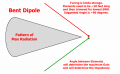
A Quarter Wavelength Vertical Radiator, with ONE Ground Plane Radial, will be very directional.
Note that this is simply a "Bent Dipole", and the angle of the bend can be adjusted to provide
an exact ~50 Ohm Load, with very low SWR.
The "Vertical" Element does not actually need to be "Vertical" at all,
in fact, the bulk of the Radiation Pattern direction will be at exactly half way between the two Elements.

If you will notice, I never refer to Commercial Products unless it is not realistic to build it yourself,
such as Coaxial Cable, or High-Spec-Capacitors, etc., unless the Commercial Parts can be had Dirt-Cheap.
But with Antennas, there's plenty of room to get creative with a $10.oo Spool of wire, and some Drywall-Screws.
For instance, with a $2.oo piece of PVC Pipe, a Roll of Masking Tape, and ~50-ft. of Wire,
you can make your own "Continuously Loaded Vertical Radiator" that can provide astounding results when
combined with 3 straight wire ~9 ft. Radials for a ground Plane, or even a Balcony Railing,
and you can make it any length you want, and it will still provide
a reasonable Radiation Pattern and reasonably low SWR.
It's not going to be a "World-Beater" in performance,
but I guarantee that it will perform better than an "Inverted-V".
.
.Directional Di-Pole Flat .pngReflectors Flat .png
 

SamR

Joined Mar 19, 2019
5,542
I'm a firm believer in "full-size" antennas or at least a fraction of one. CBers soon gave up on long mobile "whip" antennas after dragging them through low overheads a few times. So... they got the idea of keeping the frequency length but shortening the overall size by winding it around a solid fiberglass core ala rubber ducky style. Never have been fully convinced that it equals a comparable unwound antenna. The point is that they also make wound base radials as shown in my previous posts here. Which would be no great task to do with a piece of scrap PVC pipe and some insulated or magnet wire.
 

LowQCab

Joined Nov 6, 2012
5,102
SamR,
The trick with Mobile Antennas is to understand that it's not the Radiating Element that makes all the difference.
"The Ground Plane" is the other "Half" of the Antenna, which in this case, is the Car Body.
A Continuously-Loaded Fiberglass Whip, mounted in the center of the roof of the Car,
will out-perform a 9-foot Stainless Whip every time,
(that 9-foot whip will never be found mounted in the center of the roof,
it's just too impractical at something like ~13 feet or more off the ground),
the Fiberglass Loaded whip wins because it has a reasonably shaped, roughly symmetrical, Ground-Plane under it.
This creates a more uniform Radiation Pattern which you just can't get from a "Bumper-Mount" 9-foot Whip.

Any "Base-Loaded" short Antennas just generally suck.
.
.
 

LowQCab

Joined Nov 6, 2012
5,102
Darkstar
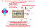
I can't believe I overlooked this Excellent Solution to an Interior CB Antenna ........
A "Quad-Loop".

Insulated Copper Wire has a "Velocity-Factor" that means that an Antenna made with it
will be slightly shorter than measurements based on a Full Wavelength in free-air.

Most Homes have ~96 to ~98 inch tall Ceilings, and most Room Walls are at, or over, 120 Inches long.
These are almost perfect dimensions for a "Full Wavelength Square Loop Antenna",
which are very efficient, and also very quiet when it comes to Reception-Noise.

They are also semi-directional, in a "Wide Figure-8 Pattern".

A single Loop is roughly 100 Ohms in Impedance,
but 2- connected together at a 90 degree Angle have a 50 Ohm Impedance, PERFECT !!!!

If fed from the center of the bottom of the Loop, the Polarization will be Horizontal,
not the preferred Polarization for CB,
but, if you feed it from one side of the Loop, in the center, it will have a Vertical Polarization,
which is what you want.
.
.In-House Quad Flat .png
 

Thread Starter

Darkstar

Joined Sep 3, 2010
182
OK, I'm going to step on somebody's toes here ...........

STOP WORSHIPING THE "GOD OF SWR".
SWR is only ONE, easy to measure, "Indicator".
It is NOT the "End-All-Be-All" "Holy-Grail" of Antenna function.
You can throw an odd piece of wire out of your window,
and then "Tune" it with a Match-Box, or what ever,
and finally wind up with a 1.1:1 SWR .
THAT DOES NOT MEAN IT WILL TRANSMIT OR RECEIVE WELL !!!!!!
It will have low Radiating Efficiency.
(and generally speaking, anything that improves Radiating Efficiency, also improves Reception to a degree )
You can also have 75 feet of cheap skinny Coax, and loose fully half your power, and still have a "perfect" SWR.
The same goes for many "compact" Antenna designs,
some of which are almost equal to a Dummy-Load,
but they can deliver an almost "perfect" SWR.
Then there are the Antennas that may "look" impressive, but radiate 75% of their Power into the Sky,
still with a "perfect" SWR.

You need to make sure that your Antenna has a Radiation Pattern
that puts the vast majority of your Signal where you want it,
which is generally down tight to the Horizon, with the Antenna as high off the ground as you can get it.
There's nothing to be gained by sending your signal into Outer-Space, (unless you're into "Skip").
So, the choices are, (in order of effectiveness) .......

Omni Directional :

Co-Linear Vertical Array,
( not practical at all on 11-Meters ),
(Huge, Really Tall, and Extremely Efficient),
( Perfect Radiation Pattern = Squashed Donut ),
( VERY Low Reception Noise ),

Bi-Cone,
( ~9 feet tall and ~20 feet in diameter ),
( can be made physically larger with great improvements ),
( Excellent Flat Radiation Pattern ),
( VERY Low Reception Noise ),

5/8 Wave Vertical Ground Plane,
( 3/4 Wavelength Radiator w/ tip folded back to create 5/8 WL dimension ),
(~22 feet tall and ~15 feet in Diameter Ground Plane ),
( Very Good "Cylindrical" Radiation Pattern ),
( Bullet-Proof Stability and SWR Levels because of 3/4 Wavelength )

1/4 Wave Vertical Ground Plane,
(~9 feet tall, ~15 feet in diameter Ground Plane),
( High Radiation Pattern),
( Noisy Reception ),

1/8th Wave Vertical with Continuously-Loaded Fiber Glass Elements,
( 6 feet X 6 feet of space),
( Virtually Spherical Radiation Pattern ),
( VERY Noisy Reception ),
Smallest form factor possible for reasonable performance on 11-Meters / 27-Mhz.
( Bullet-Proof Stability and SWR Levels because of Continuously Loaded Elements ).
( Low Gain ),

Directional Antennas,

4-Element Vertical Phased Array, Horizontally Spaced on a Common Support, on a dedicated Mast,
Takes up HUGE Space, but is an Excellent design for Vertically Polarized Reception Quality.
( VERY Low Noise Reception, because of 4 Driven Elements )
( Narrow Figure-8 Radiation Pattern ),
( ~36 feet wide, ~18 feet tall, requires substantial structural support ).

Side-Fed, 4-Element, Quad Beam,
Doable, if you have plenty of space and a dedicated Antenna Mast.
Excellent Gain,
( VERY Low Noise Reception because of "Full-Wave-Loop" design )

4-Element Vertical Yagi, almost as good as Quad-Beam above, but takes up more Vertical Space.
( can be Noisy because of only one, "Open-Ended" Driven-Element ),

A very rudimentary Directional Array can be made by using a quantity of 2 or 4 of the above described
"1/8th Wave Vertical with Continuously-Loaded Fiber Glass Elements" Antennas,
with proper 1/4 WL Spacing between Antennas and calculated Coax Phasing,
this setup can provide 2- Switchable, "Figure-8" Radiation Patterns, that are 90 degrees apart.
( Cheap and Portable, can be set up anywhere, even in an empty Grass Field ),
( as much, or slightly more Gain than full sized 1/4 WL Vertical,
( Fair Rejection of Side Signals ),
( Fair Reception Noise Rejection ),
( Wide Figure-8 Radiation Pattern )
( Self-Supporting, No Mast Required ).


There is an old saying that goes something like ........
To build a good Antenna, you have to put lots of Metal up in the Air
( I am probably mis-quoting this, but it's close )
Well, this is partially true ........
Small Antennas, (relative to the dimension of one Quarter Wavelength),
will always have poor Efficiency, and be difficult to tune, when compared to a "full-sized" Antenna.

Any time you have to "add-on" a tuning device, you can rest assured that YOU DID SOMETHING WRONG.
ANY type of Antenna Tuning Technique is just some one's weird solution to getting
20-pounds of crap into a 5-pound bag.
This is SO common with Hams that it just seems to be SOP (standard operating procedure),
because they historically were working with the lower frequencies,
which require MASSIVE Antennas to work at any kind of reasonable efficiency level.

CB Radio is in the position where a Quarter Wavelength is usually a manageable size, but still fairly large,
AND A QUARTER WAVELENGTH ANTENNA WILL "RESONATE".
Smaller than 1/4 WL Antennas must be "tricked" into resonating with add-on devices.
A 1/4 WL can Resonate whether it has a 20 Ohm Impedance, or a 450 Ohm Impedance.
It can Resonate with an SWR of 9:1.
How strongly it resonates depends upon GEOMETRY and the behavior of Electromagnetic Waves.
If it Resonates, it "might be" a good Antenna.
If it can't Resonate, it's probably not a very good Antenna, (but there are some exceptions to this rule).
SWR does NOT indicate that the Antenna is Resonating well, or Radiating any Power.
SWR just indicates whether or not a properly designed Antenna is
"playing nice" with the Feed-Line that is attached to it.
If you require any type of "Match-Box",
your Antenna will perform poorly compared to a proper design that does not require a "Match-Box".

The Graphs showing the MEASURED Radiation Strength Pattern of an Antenna is what really counts.
There is no grey area when it comes to measuring "Signal-Strength",
either it has a Radiation Pattern that is desirable, or it doesn't.
I'm not talking about "Skip" here,
that's just a strange anomaly that some people find fascinating,
OK-fine, to each his own, but that's not a reliable, repeatable, communication link,
it's just an indicator that you have a poorly focused Radiation Pattern designed into your Antenna.
Skip is possible because so many people have Antennas that Transmit and Receive well, into OUTER-SPACE.
There's nobody on another Planet, or the Moon, talking on 27-Mhz.

(I kinda got off the subject)

You need to start-off with a PROVEN Antenna design,
and then realize that any deviation from that exact design is going to reduce its EFFICIENCY,
and possibly require some kind of "unusual solution" to make it work "sort-of-ok".
An Antenna that requires a "Match-Box" will never perform as well as an Antenna that doesn't need one.
A "Match-Box" is an "unusual solution".
You would be better off with a superior Antenna Design to start with.

Many good and efficient Antenna designs do not present an exact ~50 Ohm Impedance to the Coax.
This will cause the SWR measurement to be higher than ideal.
In this type of case, you have 2 choices,
you can tolerate the SWR, and just enjoy the efficiency of your well designed Antenna,
or you can use an Impedance Transformer to more closely match the Coax Cable.
An Impedance Transformer is NOT the same as a "Match-Box".
An Impedance Transformer is simply used to change Impedances from one device to another.
A "Match-Box" is used to make a poorly designed Antenna Resonate
within the Frequency Range that you want to use the Antenna in, meaning that,
either you have an Antenna designed for the wrong Frequency Range, or just a poor Antenna design.

"Forcing" or "Tricking" an Antenna to Resonate at a different Frequency with a "Match-Box"
will ALWAYS result in poor Radiation Efficiency.

SWR is just one type of measurement of Efficiency,
this means that, if you use a "Match-Box" to get your SWR Meter to give you "the Magic Number",
you have simply "MOVED" the inefficiency from one form to a different form.
Basically, you haven't improved ANYTHING, just moved stuff around.
Well maybe ..... some Radios can't tolerate very much Reflected Power (SWR),
and will get too hot and weird-out, or fail completely, but that normally takes a Radically High SWR.
What you really need is an Antenna that doesn't require anything to be "FIXED".
Although, there is no downside to using an Impedance Transformer, if one would be advantageous.
Such as in the case of the "Bi-Cone" Antenna design I mentioned earlier.
You can design it with a narrow Included Angle (90 degrees),
to increase its Gain, and improve its Radiation Pattern, and reduce Noise,
but this will lower the Impedance that it presents to the Coax, (usually to around ~30 Ohms),
which you can either ignore, or,
you can add an Impedance Transformer to make your Radio happier,
either way, the Radiation-Pattern and EFFICIENCY, and Reception-Quality, is excellent,
with or without the Impedance Transformer,
No "Match-Box" is required,
and your Radio probably won't be upset by
the moderate ~3:1 SWR you are likely to see if you don't use any Impedance Transformer.

BTW, the Bi-Cone design is terrible for "Skip" if that's your thing.
It's very "Quiet" because it will not receive messages (or Atmospheric Noise) from Space very well.
This is due to the extremely Flat Radiation Pattern.
The Bi-Cone Antenna is a "Broad-Band" Design,
meaning that, it will work best when it
is LONGER than a Quarter Wavelength of the desired operating Frequency.
How much longer requires a stupid amount of extremely complex Math equations,
so call it 130% of a Quarter WL, or about ~12 foot long Elements.
Since it is a "Broad-Band" Antenna,
you want to be sure to have the Elements substantially longer than 1/4 WL.
The open ends of all the upper Elements should be electrically connected in a circle,
the same goes for all of the lower Elements.
The slightly "non-ideal" SWR will be consistent throughout all 40 Channels, and will not vary more than ~5%.
.
.
I don't think I ever really tried to use any antenna without a match box, ever since I made the radio. I guess someone told me I needed it so I used it. The radio instructions say to not use the radio with an SWR >=3 but 2 is tolerable. This is one reason why I depended on the match box so much. When I tried putting a 4' mobile antenna on a tripod, lifting it to my ceiling and flaring 4-6 wires in a lopsided pattern from the base across my dining room floor I had trouble getting a low SWR. This was a case where I used the 2 match box solution until one day I raised the antenna the last 3 inches and the SWR came down drastically and I could tune it with 1 match box. That was the first time I'd seen how much effect tuning could have. Another reason I've been using a match box so much is because I just wanted to see how close I could come to designing a really small antenna which, it seemed, would really need help to resonate. If I got a strong signal on my field strength meter I felt I was at least transmitting something.

I have a few questions about things you mentioned.
1. Having straight ground plane conductors must be optimal, but when there are obstacles to go around, how bad does radiation suffer if they are the correct electrical length but curve or zig-zag so that the distance from one end to the other is physically less than the length of the wire?

2. Starting with an ordinary dipole the radiation pattern is a donut with most radiation going to the sides. I tried the inverted V to save space and because it needs only 1 support, not 2. I'd heard that the radiation pattern was similar to the dipole but a bit came off the ends so it wasn't a perfect donut. Above, when you described the folded dipole (and in 3 dimensions, the bi-cone), you said the main radiation direction was midway between the arms. If that was true, the inverted V would be radiating mostly into the ground. It sounds like a much more compact way to position the antenna, vertical or horizontal, compared to having a 'corner reflector' sized for 11 meters. It also needs less linear space than adding another driven element. If the bent dipole is as directional as you say, I would use that for directionality, but in the meantime I'd rather stick with an omnidirectional quarter wave ground plane. Anyway, you said you don't care for the inverted V type of antenna. Explain what the difference is between an inverted V and a bent dipole? They sound like 2 names for the same thing, even if rotated vertically or horizontally.

I put together a quarter wave ground plane last night and hooked it up today. I heard one person for a few minutes. That's typical. I can go weeks without hearing anyone so it's been difficult to accurately estimate which of the antenna variations I've tried worked the best. This one is made of wire so the top 10'' is bent horizontal and the ground plane wires go off in whatever direction I can manage. I'm going to try to position it closer to my double balcony doors. That sounds good, but they have big metal frames, so we'll see.

It seems the antenna that worked best was the mobile antenna on a tripod with the oddly angled ground plane wires below it (~45* for a few feet then horizontal on the floor for the remainder.) A couple times I heard people talking, and at least one was in a car a good number of miles away. I have to believe he was transmitting more than 4 watts. Hopefully I'll have something similar to compare using this antenna.

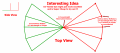
3. Has anyone tried using large metal surfaces as antenna arms as opposed to just wires to increase surface area to catch signals and radiate from? What if simple sheets of aluminum foil were hung from the arms of a dipole, as a crude example? At one point in my experiments I bought a 4'' diameter collapsible aluminum foil tube like used for vents and I used that as my driven element. The ground plane was still a wire. I didn't notice any difference in signals picked up or even the bkg noise. I expected some improvement. The bi-cone you mentioned sounds a little like this. Even the "interesting idea" you mentioned is similar but instead of a solid foil sheet it has a web of wires which is fine depending on spacing and wavelength.

I like the last idea you mentioned. That's something I'd never heard of before. I do have an outside wall (the one with the 2 balcony doors) and a living room wall at right angles to it. I'm curious to see what kind of results I can get from that kind of antenna. Hopefully the metal framed doors won't interfere too much. I'd wondered a bit about loop antennas but it seemed they were used mostly by ham operators. I haven't seen much at all about using them at 11 meters. I've also wondered what the differences, pros and cons, are between typical vertical antennas used for CB and loop antennas. They're something I haven't learned much about. From what I've seen on YouTube they are more complex and the tuning is complex also. Thanks for that idea and the diagrams, that'll be the next antenna I try.

I will pay more attention to trying to tune my current quarter wave ground plane as best I can without relying on the match box. Hopefully in the meantime I'll figure out what is causing my receiver to shift channels back and forth across the dial.
Thanks.
 
Last edited:

LowQCab

Joined Nov 6, 2012
5,102
I'll answer all your Questions in the order you asked them .........

Why are Match-Boxes so prevalent ?
When Radio was very young, the technology to use high frequencies did not exist yet,
so the Frequencies they could use were very Low,
which translates to VERY LONG Wavelengths,
which means very big Antennas.
So, the search for how to make a smaller Antenna work, at Big Antenna Frequencies,
started almost from day-one in Radio History.

A Match-Box will make an Antenna that is too small, resonate at a Big Antenna Frequency,
so the Radio Transmitter or Receiver
gets "Tricked" into believing that it is attached to a properly sized Resonating Antenna.
This magic-trick creates serious losses of efficiency all by its self,
PLUS the fact that the Antenna that it is attached to is too small for the Frequencies of interest,
creates even more loss of efficiency.

So, since "Amateur-Radio-Operators", (AKA- Hams), had a keen interest in seeing who could
out-do the other guy,
so they would continuously come up with the craziest ideas you could ever imagine to make these
massive Antennas work in their back-yard, or on top of their house.
One of the crazy ideas was the Match-Box.
This also let them use just one too-small for anything, Antenna, for a wide variety of different Frequencies.
Being able to use one Antenna for a wide range of frequencies is the Holy-Grail of Ham-Operators
so they get, or build, a Match-Box, even before the have a working Antenna to use.

If you can possibly fit a "Full Sized", (at least 1/4 Wavelength), Antenna into the space that you have available,
then you have absolutely no good use for a Match-Box.
-------------------------------------------------------------------------------------------------------------------------
Field-Strength-Meters are only useful for "Far-Field" RELATIVE Strength comparisons.
This means you need to be at least ~10 Wavelengths, (360 feet at CB Frequencies),
away from the Antenna for the reading to have any real meaning and repeatability.
( or just a quick indicator that your Transmitter is actually working ).
------------------------------------------------------------------------------------------------------------------------
When you say "Straight Ground Plane" this generally refers to having the Ground Plane Elements at
a 90 degree angle to a Vertical Radiator.
As for the exact "straightness" of the Ground Plane Elements,
the larger the number of Elements you have, and the longer they are, (more than 1/4 WL), the less it matters.
What you are creating is a fake reflection from the Earth, (the Ground),
and it can be quite fuzzy and still work fine, it's an "average" type of thing.
When you have at least 6 Ground Plane Elements, you can get away with murder.
-------------------------------------------------------------------------------------------------------------------------
Inverted "V" Antenna,
If you remember back several posts, I referred to your Inverted-V as a virtual "Dummy-Load".
A Dummy-Load is just a specially designed Resistor,
of exactly 50 Ohms,
for Transmitter Testing and Troubleshooting.
They are used when you don't actually want to Transmit anything, but need to test your Transmitter.

Some Antennas, and all Match-Boxes, to one degree or another, act like a partial "Dummy-Load".
They soak-up power, but don't deliver much power to the Air-Waves.
This s the exact definition of Antenna Efficiency, ( or NOT ).

If you will look at the picture of the "Bent-Di-Pole" that I provided, and compare that to an Inverted-V,
you will quickly get the idea that the Inverted-V is trying to blast a big hole in the ground.
Well that's EXACTLY what it is doing !!!!
It's one of those very old Ham designs that just won't go away.
It's about a 75% Dummy-Load, and the left-over 25% goes in who-knows-what direction. Really "Dumb".

Sticking with a 1/4 Wave Vertical, with a 45 degree Ground Plane, is a good plan,
but the Full Wavelength Loop Antenna has better performance,
partly because it is somewhat Directional, ( Fat Figure-8 ),
and partially because it receives MUCH less random atmospheric NOISE.
Open-Ended Elements are ALWAYS much Noisier than a Closed-Loop.

The only problem with a Loop Antenna is than it has an Impedance of around ~100 to ~120 Ohms,
but if you connect 2 of them together, and set them 90 degrees apart, (like an half-way opened book),
what you effectively wind up with is 3- Vertical Di-Poles in an Equilateral Triangle arrangement,
with a ~50 to ~60 Ohm Impedance,
and a squishy 4-Leafed-Clover Radiating Pattern, ( basically Round ).

It's just Wire, and Screw-Hooks to hold it up on the walls.
( Springs in the upper corners to pull everything tight and square would be a bonus )
The part of the Loop that has the Feed Coax in the center will be common to both Loops,
so it's really a single square Loop, one Wavelength long in circumference, (~36 feet of wire),
with 3-quarters of a second Loop attached to it, (~27 feet of wire).
( the 2 Loops need to have a very good connection to each other, preferably Soldered together ).
Small Gauge Wire would be best, because it's much cheaper, and has much less weight. ( 22-Gauge )

The Metal Frames of your Balcony Doors will be invisible to a Loop Antenna going around them.
--------------------------------------------------------------------------------------------------------------------
"" Has anyone tried using large metal surfaces as antenna arms.......... ""

Believe me, EVERYTHING has been tried, in at least 20 different configurations.

Flat Solid Metallic surfaces make good reflectors when spaced 1/2 Wavelength from a Radiating Element,
and "may" reduce received noise in some circumstances,
but they rarely make good radiators.

"Corner Reflectors" ( 90 degree Sheet Metal, or Screen, or Bars ),
and "Parabolic-Reflectors" are standard items, and work really well.

A flat sheet of metal is not the same as a Loop of wire, or even a wide single piece of wire, ( like a 2" Pipe ),
they are not even remotely close to the same thing, at least as far as an Antenna Element goes.
-----------------------------------------------------------------------------------------------------------------------
"" I'd wondered a bit about loop antennas but it seemed they were used mostly by ham operators""
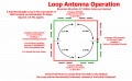
True, Loop Antennas are one of the oldest designs there is, and they are still used for good reasons.

The exact way that they work involves a lot of Math and study of
Current-Waveforms vs Voltage-Waveforms as they travel down a Wire.

I'll make you a picture that you might grasp the idea of .........

The Current and Voltage Waveforms "swap places" and "swap directions" or "Polarities"
every Quarter of a Wavelength going down any Wire or Conductor of Electricity.
Remember this Quarter Wavelength rule, it is extremely important.
---------------------------------------------------------------------------------------------------------------------
.
.Loop Antenna Operation Flat .png
 

LowQCab

Joined Nov 6, 2012
5,102
The way to think of a Quarter Wave Vertical Ground Plane Antenna ..............
Imagine that the Ground Plane Radials are a Cone shaped piece of Sheet Metal,
that has been polished to a perfectly reflective Mirror Finish,
Then step back from the Antenna, and see how you can see an up-side-down reflection of the Main Radiator.
If you can see the Reflection of the Main Radiator, it will Radiate directly towards your eyes.
Also notice that the Quarter Wave Radiator is now TWICE as long,
so it is now, effectively One Half Wavelength long.
The bigger the reflected image of the Radiator that you can see in the reflection from the Ground Plane,
from any particular Angle,
will determine how strong the Radiation Pattern will be at the point where you Eyes are.
.
.
 

Thread Starter

Darkstar

Joined Sep 3, 2010
182
The way to think of a Quarter Wave Vertical Ground Plane Antenna ..............
Imagine that the Ground Plane Radials are a Cone shaped piece of Sheet Metal,
that has been polished to a perfectly reflective Mirror Finish,
Then step back from the Antenna, and see how you can see an up-side-down reflection of the Main Radiator.
If you can see the Reflection of the Main Radiator, it will Radiate directly towards your eyes.
Also notice that the Quarter Wave Radiator is now TWICE as long,
so it is now, effectively One Half Wavelength long.
The bigger the reflected image of the Radiator that you can see in the reflection from the Ground Plane,
from any particular Angle,
will determine how strong the Radiation Pattern will be at the point where you Eyes are.
.
.
I must compliment you on the thoroughness of your answers. The diagrams help a lot with details.

I understand things now what I wasn't seeing before about how antennas operate. I do like to understand things as much as possible.

I just have a few comments/observations.
Since you mentioned dummy loads, it reminded me of when I was making some dummy loads with a cap and diode so I could get a relative voltage reading from each. There were some that just didn't want to work right, I always got strange results when I used them. One in particular involved making my 50 ohm, 5 watt dummy from five 10 ohm, 5 watt resistors strung in series. I positioned them to minimize field interaction between adjacent resistors. Each was maybe 2'' long. I know it's best to make connections as short as possible, so I thought maybe the total path length was too long. I used different resistors and got good results. Then I saw some YouTube videos of guys making high wattage loads and they might have a large number of resistors wired together, with a path length many times what mine was. I've wondered why that is. I'm obviously missing some piece of the puzzle here.

Another idea that failed several times is I tried to make a tuneable dummy load with ordinary carbon composition pots. I'd adjust the antenna for lowest SWR then connect the dummy. They were never equal so I'd adjust the dummy to get the same SWR as I got with the antenna. I figured it'd give me a measure of the non-inductive impedance of the antenna. Knowing this I could make changes to the antenna to get the impedance to equal 50-52 ohms. I'd make the dummies with a resistance of from about 30 to 100 ohms but they always wanted to adjust down to a lower resistance than I could tune them for and I wouldn't even be very close to the antenna's SWR. I got the same results with different wiring of the dummies. I don't know what this means but it was a surprising result. I'm also surprised it didn't work.

You say the loop antenna has a low noise level. that sounds good to me (no pun intended) as my bkg noise level is often about 5 or half way up the scale on my little meter. This isn't even counting something in the area that turns on randomly and could be on for days at a time. The signal is very high amplitude, highly overmodulated and bleeds over more than half of my 23 channels and can also be picked up on an old analog radio between stations on both AM and FM bands. I get it in my car too with a modern radio. It's as if it is made to prevent communication on many frequencies or possibly hide some kind of communication. As odd as this sounds, I tried to localize the source one evening and found that it is strongest on my block, maybe even from my own building. If I go down the street it goes away. I think other residents have complained of interference within the past year or two. I haven't found any way to localize it further. A simple old transistor radio would do it but I don't have one. I can turn off everything at my breaker box and it persists so I know it's not me. It turns on and off and changes frequency regardless of what I'm doing. I have to find help tracking this down.

On the reflectivity of the 2 wall loop antenna, this reminds me of a corner reflector that can be made from 3 mirrors, each perpendicular to the others, like the corner of a room formed by 2 walls and a ceiling. This is also directional with the additional property that it reflects any incoming light back in the same direction it came from, regardless of angle. A panel of these reflectors was left on the moon by some of the first astronauts so the moon's distance could be measured by timing laser pulses. It seems like it may be more directional than the 2 panel reflector, but I don't know what advantage it would have for radio communication, or even just transmission in general.

To measure the wire for the loop antenna, I know I have to calculate the length according to the velocity factor of the wire which is less than a signal traveling in a vacuum. The number I've used, as I recall, is 468/frequency in MHz = a half wavelength of wire in feet. I have a lot of 14 and 16 gauge paired, insulated speaker wire. The insulation further reduces the velocity factor by a few percent but I haven't heard any solid numbers for this, only guesses, even by people lecturing on the subject. They might say bare copper has a velocity factor of 95% and insulated wire might be 92% as an example. How do you suggest I calculate the length? I've also heard there are continuing arguments over which is better to use, solid copper or stranded. I suppose the argument being that stranded has higher surface area but the signal would also have to move from one strand to another to stay on the outermost surfaces. One could also use 2'' wide aluminum duct tape which has a large surface area too. I'm not concerned about this, it's just an observation.

Thanks.
 

LowQCab

Joined Nov 6, 2012
5,102
Dummy-Loads are not "just" a resistor.
RF-Current has its own set of rules, and even then,
those rules change with Frequency,
and whether you're looking at it cock-eyed, and whether you're holding your mouth right.

Store-Bought is the only way to go for accurate Testing Equipment,
and even some Store-Bought stuff is not reliable.
If you build your own Test Equipment,
it should be verified with quality Store-Bought Equipment,
otherwise you're just throwing more possible confusion into the mix.
Even proper "Vector Signal Analyzers" are becoming inexpensive.
( this is what you really need if you decide to get serious with Antenna Design )

The first thing you need to do when testing, is to make sure that you have done your research.
You need to know what Impedance RANGE to to expect from the Antenna design that you have selected.
As well as the results that other people have had, or what they "claim", with similar designs.
All the small Tweaks have the potential to make some kind of difference, good or bad,
and, you need to have some idea of what you "SHOULD" expect
from any particular change, and then measure what you "ACTUALLY" get
in the real world of YOUR particular set of circumstances.
The results might matter to you, or they might be totally inconsequential in the big picture.
And remember, these are "trends" towards a goal, and "should cause this" scenarios,
because nothing is "engraved-in-stone" with RF, and the higher the Frequency, the more weird it gets.
The higher the frequency gets, the more RF starts acting like some kind of
"Invisible Light" that likes to travel down conductors,
and there are things that "likes", and things that it doesn't "like",
and somehow, if you treat it right, you might get it to convert into Electromagnetic Waves at some point.
Luckily, 27-Mhz is a sort-of-mid-to-low-frequency, ( by today's standards ),
so about half of the the time, it acts like normal electricity,
other times, it does its own thing, whether you like it, or not.

There are scads of complex Math Formulas that will tell you what it is "supposed-to-do",
and then there's the actual results, which don't always match-up with the Math.
Some people get totally caught-up in having perfect Math Numbers,
but there's a lot of "Fudge-Factors" that enter into the equation,
this means that the Math is mostly useful for "pointing you in the right direction".
So, you can have situations where the Math says it shouldn't work, but it works just fine anyway.
"Your mileage may vary".

Antennas are like the 24" Drag-Slicks on a Top-Fuel-Dragster,
if you put cheezy -"$69.oo-for-a-set-of-4"- tires on that Dragster,
it will just make a lot of smoke and noise, and go nowhere.
------------------------------------------------------------------------------------------------------------------

Don't worry about getting "exactly" 50-Ohms Impedance.
It's not magic.
Your Radio may not have an exact 50-Ohm interface.
Now that I think of it, didn't you say somewhere that you have a TUBE Radio ???
Tube Radios are really squishy things at times, and quite often need a
proper "Alignment" done on them to achieve their stated performance.
If that was you, you would be better off buying a $49.oo, modern, Solid-State-Radio for Testing purposes.
You can probably get one used for ~$20 bucks.
Or go to a Yard-Sale and get one for ~$5 bucks.
You are throwing a bunch of possible confusion into things if your Radio is not "Spot-On".
After you get your Antenna and Coax sorted-out, using a KNOWN GOOD and STABLE Radio,
THEN you can play with your Tube Baby.

If you can get an SWR of less than 2:1, don't do anything further,
you're just as likely to reduce the overall system Efficiency, as you are to improve it.
Keep in mind that your Coax MUST BE very Close to 12.5 feet long,
1/2 Wavelength X the "Velocity-Factor" of your particular Coax Cable,
which is probably in the range of 0.7, ( I'm guessing ),
0.7 X 10.9 Meters = 7.63 Meters, 7.63 Meters / 2 = 3.815 Meters for 1/2 WL, or 12.5 Feet,
otherwise you have no idea of what the the hell is going on.

Your SWR Meter should be connected to your Radio with a very short piece of Coax, maybe 6 inches.
Your SWR Meter should read exactly the same when you hook it up backwards,
if it doesn't, fix it, or throw it away. ( they are quite simple so you should be able to re-build it )
Your SWR Meter should read very close to 1:1 when it has a Store-Bought Dummy-Load attached,
if it doesn't, fix it, or throw it away.
Get a Female to Female Coax Coupling, and attach it to the Antenna-End of your 12.5 foot Coax.
Screw the Store-Bought Dummy-Load into the Coupler,
test SWR,
you should get exactly the same SWR Readings that you got with
the Dummy-Load directly attached to the SWR Meter.
If you don't get exactly the same readings, you must replace your Coax run with a new one,
preferably a custom ordered length, professionally manufactured Coax Cable, ( ~$10 to ~$15.oo ).
( On a short run like this, you don't need an expensive, "Low-Loss" Cable )

Now you have a worthy Tool to use, and a known good Coax Cable.
Now, you can be reasonably sure that,
every anomaly that you measure and observe should be Antenna related.
Now you can work on Tuning your Antenna, ( if necessary ).
Once you have done everything that you can do to the Antenna to reduce the SWR,
and the SWR is still not below 2:1,
next you can create a set of ~4 or ~5 individual Coax Cables
that are cut to various fractions of a 1/4 Wavelength, ( Times the Velocity-Factor of your Coax ).
Try each piece of Coax, either by its self, or in addition to, your Main Coax run,
and measure the SWR for each one,
keep the one with the lowest SWR reading.
If you are still over 2:1, but below 3:1, you could reasonably call the Job Done, and feel happy about it.
You now have a pretty solid system in place, and you won't be able to detect that it's not exactly perfect.
If you are so Anal about SWR, that you just can't stand it not being ZERO,
there are more involved and complex ways of reducing SWR, ( without a Match-Box ),
which involve too much Math to go into here.
-------------------------------------------------------------------------------------------------------------------
A Bicycle Reflector works on the same principle,
but it's not generally useful for any RF application that I am aware of.
-------------------------------------------------------------------------------------------------------------------
Those are good average V.F. numbers for standard Copper Building Wiring with "THHN" Insulation).
I normally use 90% with good results.
Coax, on the other hand, is manufactured specifically with a certain Velocity-Factor Specification
which is normally very close to accurate, age, and physical wear, can change it though.

Stranded or Solid Wire makes zero difference at the frequencies in question, ( 27-Mhz ).
The Diameter, or Gauge#, does make a slight difference though.

The Aluminum Duct Tape will produce unpredictable results, or do nothing at all.
It works well for Shielding Sensitive Circuitry from RF Interference though.
-------------------------------------------------------------------------------------------------------------------
.
.
 
Last edited:

Thread Starter

Darkstar

Joined Sep 3, 2010
182
Dummy-Loads are not "just" a resistor.
RF-Current has its own set of rules, and even then,
those rules change with Frequency,
and whether you're looking at it cock-eyed, and whether you're holding your mouth right.

Store-Bought is the only way to go for accurate Testing Equipment,
and even some Store-Bought stuff is not reliable.
If you build your own Test Equipment,
it should be verified with quality Store-Bought Equipment,
otherwise you're just throwing more possible confusion into the mix.
Even proper "Vector Signal Analyzers" are becoming inexpensive.
( this is what you really need if you decide to get serious with Antenna Design )

The first thing you need to do when testing, is to make sure that you have done your research.
You need to know what Impedance RANGE to to expect from the Antenna design that you have selected.
As well as the results that other people have had, or what they "claim", with similar designs.
All the small Tweaks have the potential to make some kind of difference, good or bad,
and, you need to have some idea of what you "SHOULD" expect
from any particular change, and then measure what you "ACTUALLY" get
in the real world of YOUR particular set of circumstances.
The results might matter to you, or they might be totally inconsequential in the big picture.
And remember, these are "trends" towards a goal, and "should cause this" scenarios,
because nothing is "engraved-in-stone" with RF, and the higher the Frequency, the more weird it gets.
The higher the frequency gets, the more RF starts acting like some kind of
"Invisible Light" that likes to travel down conductors,
and there are things that "likes", and things that it doesn't "like",
and somehow, if you treat it right, you might get it to convert into Electromagnetic Waves at some point.
Luckily, 27-Mhz is a sort-of-mid-to-low-frequency, ( by today's standards ),
so about half of the the time, it acts like normal electricity,
other times, it does its own thing, whether you like it, or not.

There are scads of complex Math Formulas that will tell you what it is "supposed-to-do",
and then there's the actual results, which don't always match-up with the Math.
Some people get totally caught-up in having perfect Math Numbers,
but there's a lot of "Fudge-Factors" that enter into the equation,
this means that the Math is mostly useful for "pointing you in the right direction".
So, you can have situations where the Math says it shouldn't work, but it works just fine anyway.
"Your mileage may vary".

Antennas are like the 24" Drag-Slicks on a Top-Fuel-Dragster,
if you put cheezy -"$69.oo-for-a-set-of-4"- tires on that Dragster,
it will just make a lot of smoke and noise, and go nowhere.
------------------------------------------------------------------------------------------------------------------

Don't worry about getting "exactly" 50-Ohms Impedance.
It's not magic.
Your Radio may not have an exact 50-Ohm interface.
Now that I think of it, didn't you say somewhere that you have a TUBE Radio ???
Tube Radios are really squishy things at times, and quite often need a
proper "Alignment" done on them to achieve their stated performance.
If that was you, you would be better off buying a $49.oo, modern, Solid-State-Radio for Testing purposes.
You can probably get one used for ~$20 bucks.
Or go to a Yard-Sale and get one for ~$5 bucks.
You are throwing a bunch of possible confusion into things if your Radio is not "Spot-On".
After you get your Antenna and Coax sorted-out, using a KNOWN GOOD and STABLE Radio,
THEN you can play with your Tube Baby.

If you can get an SWR of less than 2:1, don't do anything further,
you're just as likely to reduce the overall system Efficiency, as you are to improve it.
Keep in mind that your Coax MUST BE very Close to 12.5 feet long,
1/2 Wavelength X the "Velocity-Factor" of your particular Coax Cable,
which is probably in the range of 0.7, ( I'm guessing ),
0.7 X 10.9 Meters = 7.63 Meters, 7.63 Meters / 2 = 3.815 Meters for 1/2 WL, or 12.5 Feet,
otherwise you have no idea of what the the hell is going on.

Your SWR Meter should be connected to your Radio with a very short piece of Coax, maybe 6 inches.
Your SWR Meter should read exactly the same when you hook it up backwards,
if it doesn't, fix it, or throw it away. ( they are quite simple so you should be able to re-build it )
Your SWR Meter should read very close to 1:1 when it has a Store-Bought Dummy-Load attached,
if it doesn't, fix it, or throw it away.
Get a Female to Female Coax Coupling, and attach it to the Antenna-End of your 12.5 foot Coax.
Screw the Store-Bought Dummy-Load into the Coupler,
test SWR,
you should get exactly the same SWR Readings that you got with
the Dummy-Load directly attached to the SWR Meter.
If you don't get exactly the same readings, you must replace your Coax run with a new one,
preferably a custom ordered length, professionally manufactured Coax Cable, ( ~$10 to ~$15.oo ).
( On a short run like this, you don't need an expensive, "Low-Loss" Cable )

Now you have a worthy Tool to use, and a known good Coax Cable.
Now, you can be reasonably sure that,
every anomaly that you measure and observe should be Antenna related.
Now you can work on Tuning your Antenna, ( if necessary ).
Once you have done everything that you can do to the Antenna to reduce the SWR,
and the SWR is still not below 2:1,
next you can create a set of ~4 or ~5 individual Coax Cables
that are cut to various fractions of a 1/4 Wavelength, ( Times the Velocity-Factor of your Coax ).
Try each piece of Coax, either by its self, or in addition to, your Main Coax run,
and measure the SWR for each one,
keep the one with the lowest SWR reading.
If you are still over 2:1, but below 3:1, you could reasonably call the Job Done, and feel happy about it.
You now have a pretty solid system in place, and you won't be able to detect that it's not exactly perfect.
If you are so Anal about SWR, that you just can't stand it not being ZERO,
there are more involved and complex ways of reducing SWR, ( without a Match-Box ),
which involve too much Math to go into here.
-------------------------------------------------------------------------------------------------------------------
A Bicycle Reflector works on the same principle,
but it's not generally useful for any RF application that I am aware of.
-------------------------------------------------------------------------------------------------------------------
Those are good average V.F. numbers for standard Copper Building Wiring with "THHN" Insulation).
I normally use 90% with good results.
Coax, on the other hand, is manufactured specifically with a certain Velocity-Factor Specification
which is normally very close to accurate, age, and physical wear, can change it though.

Stranded or Solid Wire makes zero difference at the frequencies in question, ( 27-Mhz ).
The Diameter, or Gauge#, does make a slight difference though.

The Aluminum Duct Tape will produce unpredictable results, or do nothing at all.
It works well for Shielding Sensitive Circuitry from RF Interference though.
-------------------------------------------------------------------------------------------------------------------
.
.
Your comment about invisible light that likes to travel down conductors reminds me of a physics class in college in 1971. The teacher was talking about EM waves, etc and I realized there would be a point where the signals would want to stop traveling in a conductor and begin radiating like light as the frequency increased. I asked the teacher about this. I think he said something about the signals radiating from the wires and they could be guided by wave guides like microwaves, and after that we just jumped past the confusing frequencies to using all optics.

You also talk about what should happen not always being what does happen. In about 1977, when I wanted to put my half wave antenna in my not-quite-high-enough attic I didn't know what the best solution was. I went to a Motorola facility near me t get advice from an expert. A guy actually invited me to his office and we discussed the problem. The main point he made was that antenna design is a bit art and a bit science. The same thing you are saying , take your best guess, and add whatever fudge factor makes it work. The same thing happens in a lot of other fields too. Nobody knows exactly what makes a process work, all they know is if the machine is set up like this, we get the right kind of product out. Kind of makes you wonder how such high tech electronic devices can be made at all with that kind of understanding. The usual comparison is how people do just fine driving a car without understanding how its parts work.

I thought of aluminum duct tape because I remembered how wide braid is used for lightning grounding because it has a larger surface for the current to spread out on. Not the same as weak radio signals, but the signals still travel on the surface so the thickness shouldn't have much effect.

I finished the 1/4 wave gnd plane & did a bunch of tuning. It started with an SWR of about 6 or 7 (way into the red, half way between 3 and infinity.) It started with 4 radials. They liked 104'' length. With the match box the SWR was 1.4:1 or less across the dial. Then I doubled that length and the SWR went down and became flatter across the band. (Oh, BTW, I do have a transistor CB from 1979 which I use to help check the older one.) I also found it did better with more radials so it now has 12 half wave radials. I was getting at least a mile with the 4 short radial version. Now it receives better. With the antenna cable connected to the SWR meter without the match box, the SWR has dropped from 6 or 7 to about 3 across the dial. Wit the match box it is flat across 40 channels. It is in front of my balcony doors and the radials are all on one side going the length of my dining and living rooms. In that direction is an expressway about a mile away at the closest point. I was listening to the truckers commenting on the reckless people driving their cars in the snow.

When I use the match box for tuning, I watch my field strength meter and tune for max signal rather than lowest SWR. They don't occur in the same places.

About the loop antenna. I may not be able to make that as it should be. The wall my balcony is on, with 2 big doors, is over 17 feet long but my ceiling is only 8 feet high so I can't make a square without bending it somehow. The vertical delta loop is also out. I'm assuming each leg is 1/3 wavelength. The 8' ceiling is the limitation.

This old tube radio I'm working on has sentimental value from when I was in high school, that's why I want to get it working. It's been fine any time I used it over the years but things kept changing this year. The audio output tube looks different now than it did in July and the frequency drift just started in November. I still have few clues as to what's going on.
I'll attach a photo taken this past July showing the blue glow in the 12AQ5 audio output tube. It has always been there. Last month I noticed it had disappeared about the time the frequency drift & noise began.

Thanks again for all your great info. Have a happy and safe new year.Blue Tube Glow, July 2020, gone now.jpg
 

SamR

Joined Mar 19, 2019
5,542
The trick is to tune the antenna and there are several methods to do so. We used to have Dip Meters to determine the center frequency of an antenna and try to tune the antenna for that to be the center of the band we were going to transmit on. Of course, after the antenna is installed and somewhat unreachable then it needed an inline antenna tuner for any further adjustments. Now, it's the NanoVNA Vector Network Analyzer 【Upgraded】AURSINC NanoVNA Vector Network Analyzer 10KHz -1.5GHz HF VHF UHF Antenna Analyzer Measuring S Parameters, Voltage Standing Wave Ratio, Phase, Delay, Smith Chart(Latest Version REV3.4): Amazon.com: Industrial & Scientific which is a whole lot better than a dip meter. Cheaper when bought directly from the source in china.
 

LowQCab

Joined Nov 6, 2012
5,102
The Loop Antenna does not have to be exactly square.
It can be 8 X 10 without much noticeable difference in performance or tuning.
Think of it as 2 Di-Poles, slightly further apart than 1/4 WL,
with 6- inches of the top tip, and bottom tip, bent at a 90 degree angle,
this is only a small percentage of the overall Radiating Element,
add to this, that the Current that flows at the tips of these 2 Di-poles is quite low,
and goes to almost zero by the time you get half way between the Vertical Legs.

To give you an idea of how squishy Antennas can be,
a perfect Circle works just as good as a Square,
and a Triangle is not far behind,
which seems to defy the accepted, basic explanation, about how a Loop Antenna works,
and to top-off all that, when you get into lower frequencies,
how far you are above the ground, (measured in Wavelengths),
starts having a serious effect on how the Antenna performs, (or not),
it also affects SWR, Impedance, and Radiation Patterns,
which is why Hams ALWAYS have some sort of Match-Box,
not only are they trying to cover a huge frequency range with one Antenna,
the antenna is almost always too small compared to a Wavelength,
and too close to the Ground compared to a Wavelength,
so, the fact that they get the damn thing to work at all is a miracle.

On the other hand .........
When working with CB Frequencies, you are much better off accomplishing all of your
Antenna Tuning by making physical adjustments to the Antenna its self until you get
an acceptable level of Resonance, ( SWR and Impedance), along with an acceptable Radiation Pattern.
When you make these Tuning changes directly to the Antenna or the Coax,
instead of seeing if you can get it to work with a Match Box,
you wind-up with a far more elegant, efficient, simple, and generally higher performance, "System".
A Match Box can make a Chain-Link Fence work as an Antenna,
its performance will be very poor, but you can probably achieve an almost perfect SWR.
When a properly Tuned Antenna is used, there is zero need for a Match Box to "Fix" things.
A Match Box will always introduce its own losses, even when used with a perfect Antenna,
and the further out of Tune the Antenna is, the more losses the Match Box introduces into the mix.

Ideally, you want the Antenna to "act like" a 50-Ohm Resistor, (which is never gonna happen).
If the Antenna is "short" it will act like a Capacitor,
if the Antenna is too "long" it will act like an Inductor.
The Antenna is trying to simulate a Resistor using a specific balance of Inductance and Capacitance,
this is specifically why the Antenna is said to have "Impedance" rather than "Resistance".
Actually, the DC-Resistance on many Antennas is almost zero Ohms, or a direct "Short",
but the "Impedance" may be ~700 Ohms, or even "infinite", at a certain High-Frequency range.

The "Impedance" is what you are tweaking with a Match Box,
this is done by adding or subtracting Capacitance, and/or, Inductance,
both in Series with, and/or, in Parallel with, the Antenna.

The ideal Impedance can be achieved by simply altering the "Length" of the Antenna by a small amount,
or altering the length of the Coax, which should only be "the back-up plan",
and only resorted to after all Antenna adjustments have been tried,
but you still have some minor SWR issues that you would like to minimize.

Having to "add" some kind of Tweaking Device to the Antenna to get it to work,
is a sure indicator that the Antenna is poorly matched to the Frequency that you are using.
The only time that this is an acceptable solution is when you only have practical space for one Antenna,
but you are working with a wide range of different Frequencies.
This is why Hams use Match Boxes,
which are actually a liability when using only a narrow Frequency Range.

BTW, that 1979 CB Radio is not what I had in mind when I said "Modern".
Capacitors, especially cheap ones, and/or, older designs, have a finite life expectancy,
same goes for most of the other components.
I was referring to "Complete-Radio-on-a-Chip" type of Modern,
something that is extremely stable, and reliable,
with designed in protection features so you can't smoke it if something goes wrong.
Just like with your old Tube CB Transceiver, it's a miracle that it actually still functions with no smoke.

But I would like to add that .......
Tube Gear is easily tweakable, and when it is in good working order,
"CAN" have superior modulation characteristics,
that doesn't mean that it automatically does though,
just that they are usually easy to tweak to easily deliver ~125% modulation of the "Positive-Peaks".
Most transistorized CB Radios have very limited modulation of the "Positive-Peaks",
where the nominal ~4-Watts of RF output power "should" temporarily go to ~8-Watts or more.

( only over modulation of the "Negative-Peaks" causes unwanted interference on adjacent channels)
.
.
 

Thread Starter

Darkstar

Joined Sep 3, 2010
182
The trick is to tune the antenna and there are several methods to do so. We used to have Dip Meters to determine the center frequency of an antenna and try to tune the antenna for that to be the center of the band we were going to transmit on. Of course, after the antenna is installed and somewhat unreachable then it needed an inline antenna tuner for any further adjustments. Now, it's the NanoVNA Vector Network Analyzer 【Upgraded】AURSINC NanoVNA Vector Network Analyzer 10KHz -1.5GHz HF VHF UHF Antenna Analyzer Measuring S Parameters, Voltage Standing Wave Ratio, Phase, Delay, Smith Chart(Latest Version REV3.4): Amazon.com: Industrial & Scientific which is a whole lot better than a dip meter. Cheaper when bought directly from the source in china.
I appreciate the info. I remember being interested in a dip meter way back when. 10 years ago I might have put some money into this, but this is not a full time hobby so I don't want to buy new high tech equipment. I already have 2 bedrooms strictly for the storage of hobby stuff, not sleeping, which I'm trying to empty. Now I have an antenna the size of my living room, dining room and part of the kitchen combined. I'm experimenting because I'm bored, it's nicer than cleaning stuff out & it's not easy finding people who understand high tech stuff, much less want to buy it. I tried for 3 years to catalog it all and gave up. I sent a friend a ''partial'' list of items and it totaled 500 MB. I have so much stuff already and I'm just killing time when I can't sleep that's why I experiment so much and try to make what I can with what I have. If there was a single store where I could buy parts I would go there 10 times a day if I had to and I could get more involved in this. Ordering online is orders of magnitude slower. I refuse to pay extra to wait a week every time I want to connect a device into the circuit to see if it works like I want. I like to experiment and improvise. I like taking something and learning how to make it a bit better. Reminds me of a line I like in a movie called "Bats" in which a guy says "I'm a scientist, that's what we do, we make everything a little better." Referring to his latest experiment, which happened to be out of control at the time.

I may put one CB in my car if I need to travel this winter so I can get info on traffic conditions. I could spend mucho bucks on a smart phone with GPS, etc. but then Google will know where I am, and even where I'm going, better than I do. This is more fun.
Thank you and Happy New Year.
 

SamR

Joined Mar 19, 2019
5,542
At the bare minimum, set the transmit channel to mid-band or to the channel you will be using the most. With a good SWR meter (not the one on the radio) observe the reading while transmitting and add or subtract wire to the antenna to bring it as close to 1:1 as you can. I assume you are using a balun to connect the 50Ω impedance transmitter output to the antenna. In the end though, all you will have is access to the CB airwaves and all that entails. Which is pretty dismal...
 
Top