Facebook
 Google
 GitHub
 Linkedin


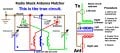
Kinda humorous that the guy in the Attic Article quoted above
was so meticulous about removing the exact same number of turns from BOTH Antennas
when the "Ground Plane" Antenna is somewhere around ~3.5" longer than
the Main Radiator because of that substantial steel Mounting Bracket that he fabricated.
He could have also picked-up ~3 to 5db of Gain by creating a proper 45 degree Ground Plane
using plain Copper Wires, ( at least 3 of them, and more is always better),
that are at least 9+ feet long,
attached to his nice steel Bracket,
and then spread-out across the Attic,
and secured with a nail to any convenient Ceiling Rafter.
This will work perfectly well,
there is no need for the Ground Plain, ( or "counter poise" element ),
to be an exact mirror image of the Main Driven Element.
But it is very important that it is effectively 9+ feet long, so as to resonate well with the Driven Element.
Ground Planes are very interesting in that,
as long as the Radials are at least 1/4 Wavelength long, or more,
and there are at least 3 of them,
then the exact length of the Radials will have little effect on SWR,
but can have a very large effect on Radiation Pattern, and overall Antenna Radiating Efficiency.
These effects improve all the way up to 3 Wavelengths in Radius, away from the Driven Element,
but past 3 Wavelengths, there is very little measurable improvement .
Using a Loaded Main Radiator may be necessary when space is limited,
but it causes the Radiation Pattern to be much higher than is desirable for Local Communication use,
which needs to be as low and flat to the Horizon as possible,
but instead, tends to substantially favor Skip communication.
The solution to this is to create a "Bi-Cone" Antenna, where there are multiple Radiators arranged
in a mirror image of the 45 degree Ground Plane Radials.
This type of Antenna has excellent Gain, and typically very low SWRs, over a broad band of frequencies,
and high immunity to Atmospheric Noise which plagues most Vertically Polarized Antennas,
and are generally described as a "Broad-Band" Antenna.
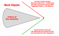
The Impedance of a Bi-Cone Antenna is directly related to the Included Angle between
the Driven Elements, and the Ground Plane Elements.
90 degrees results in roughly ~30 Ohms,
135 degrees results in roughly ~50 Ohms,
and 180 degrees is a Di-Pole Antenna, which has Roughly ~75 Ohms Impedance.
The SWR will, of course, be the lowest at ~50 Ohms,
but this may not provide the best possible performance from this Antenna,
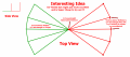
as the Gain increases substantially, (as much as ~6db), as the Included Angle approaches 90 degrees,
and has an extremely FLAT Radiation Pattern,
achieving the best Omni-Directional Pattern possible for Local Communications.
.
.
was so meticulous about removing the exact same number of turns from BOTH Antennas
when the "Ground Plane" Antenna is somewhere around ~3.5" longer than
the Main Radiator because of that substantial steel Mounting Bracket that he fabricated.
He could have also picked-up ~3 to 5db of Gain by creating a proper 45 degree Ground Plane
using plain Copper Wires, ( at least 3 of them, and more is always better),
that are at least 9+ feet long,
attached to his nice steel Bracket,
and then spread-out across the Attic,
and secured with a nail to any convenient Ceiling Rafter.
This will work perfectly well,
there is no need for the Ground Plain, ( or "counter poise" element ),
to be an exact mirror image of the Main Driven Element.
But it is very important that it is effectively 9+ feet long, so as to resonate well with the Driven Element.
Ground Planes are very interesting in that,
as long as the Radials are at least 1/4 Wavelength long, or more,
and there are at least 3 of them,
then the exact length of the Radials will have little effect on SWR,
but can have a very large effect on Radiation Pattern, and overall Antenna Radiating Efficiency.
These effects improve all the way up to 3 Wavelengths in Radius, away from the Driven Element,
but past 3 Wavelengths, there is very little measurable improvement .
Using a Loaded Main Radiator may be necessary when space is limited,
but it causes the Radiation Pattern to be much higher than is desirable for Local Communication use,
which needs to be as low and flat to the Horizon as possible,
but instead, tends to substantially favor Skip communication.
The solution to this is to create a "Bi-Cone" Antenna, where there are multiple Radiators arranged
in a mirror image of the 45 degree Ground Plane Radials.
This type of Antenna has excellent Gain, and typically very low SWRs, over a broad band of frequencies,
and high immunity to Atmospheric Noise which plagues most Vertically Polarized Antennas,
and are generally described as a "Broad-Band" Antenna.
The Impedance of a Bi-Cone Antenna is directly related to the Included Angle between
the Driven Elements, and the Ground Plane Elements.
90 degrees results in roughly ~30 Ohms,
135 degrees results in roughly ~50 Ohms,
and 180 degrees is a Di-Pole Antenna, which has Roughly ~75 Ohms Impedance.
The SWR will, of course, be the lowest at ~50 Ohms,
but this may not provide the best possible performance from this Antenna,
as the Gain increases substantially, (as much as ~6db), as the Included Angle approaches 90 degrees,
and has an extremely FLAT Radiation Pattern,
achieving the best Omni-Directional Pattern possible for Local Communications.
.
.