Camera trigger --> multivibrator

Thread Starter

Arne1996

Joined Feb 15, 2017
21
Hello everyone!
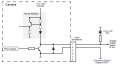
I'm a student busy with a project and my deadline is incoming. I'm a little stuck with triggering my multivibrator with the camera. I use a 6-pin connector of the camera with a GPIO pin. The schematic of the camera from the datasheet is below:
upload_2017-5-26_13-13-30.png
To trigger my multivibrator I need a voltage of 5V. My multivibrator works if I just trigger it with a voltage of 5V. This is the schematic:
upload_2017-5-26_13-19-21.png
So as you can see if I connect those two schematics, I would have a voltage devider. I already tried to connect 12V and devide the voltage so there is 5V on the trigger pin but it doesn't work... I think I'm not seeing something important. The resistor of 1Kohm is needed (pull down resistor) to let my multivibrator work... Someone who can help me?
Thanks in advance!
 

Attachments

GopherT

Joined Nov 23, 2012
8,009
According to the "timing diagram" on the chips DATASHEET, a high output is triggered by:
- bringing the "A" pin from high to low while the B pin is high (see dotted lines from A below).
-or-
- bringing the B pin from low to high while A is low.

The bringing the clear pin low will prematurely end the output pulse.

Note the double-pulse on the A pin, extends the output ( means the output is "retriggerable")

Your issue is that your trigger is connected to the clear, it should be connected to the B pin. Keep the clear pin high in your application.


image.png
 

Thread Starter

Arne1996

Joined Feb 15, 2017
21
According to the "timing diagram" on the chips DATASHEET, a high output is triggered by:
- bringing the "A" pin from high to low while the B pin is high (see dotted lines from A below).
-or-
- bringing the B pin from low to high while A is low.

The bringing the clear pin low will prematurely end the output pulse.

Note the double-pulse on the A pin, extends the output ( means the output is "retriggerable")

Your issue is that your trigger is connected to the clear, it should be connected to the B pin. Keep the clear pin high in your application.


View attachment 127610
according to this function table, it is also possible to trigger on the CLR pin?
upload_2017-5-26_14-30-40.png
I was more asking how to fix the problem between the monostable multivibrator and the camera because if I test the multivibrator without the camera and I push a wire physically too the trigger, the monostable gives me the pulse on the output. So I dont think it is the monostable multivibrator?
or am I wrong?
 

GopherT

Joined Nov 23, 2012
8,009
according to this function table, it is also possible to trigger on the CLR pin?
View attachment 127618
I was more asking how to fix the problem between the monostable multivibrator and the camera because if I test the multivibrator without the camera and I push a wire physically too the trigger, the monostable gives me the pulse on the output. So I dont think it is the monostable multivibrator?
or am I wrong?
clear is not an appropriate "trigger" (from high to low transistion, or, low to high transistion), clear is a "state" meaning that the output cannot be high if the "clear" pin is low.

It also shows that the trigger (arrow in A or B pins) can only work if the "clear" pin is high.

You should trigger with the A or B pins.

EDIT: you are right - now I see the last line. That seems more like an unresolved glitch than a feature.
 

Thread Starter

Arne1996

Joined Feb 15, 2017
21
Today I may figured something out. I tried a schematic to trigger my monostable multivibrator and I think it should work but is it possible that my trigger pulse so short is (5 ms) that my multivibrator doesn't respond? Because now the camera turns on every second for 5ms or maybe like @GopherT told, I used to wrong pin to do applications like that? I hope anyone can help me before my deadline ends...
NOTE: left is the camera and right the multivibrator
18767031_10210962190185774_98623011_o.jpg
thanks in advance!
 
Top