Calculating This Circuits Frequency

Thread Starter

Wendy

Joined Mar 24, 2008
23,415
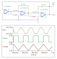
I came up with this circuit when I was in college, and at the time I thought I had figured it out. SgtWookie SPICED it, and I've been using it as a check for trying to calculate what the frequency of the oscillator should be, with no success to date.


http://forum.allaboutcircuits.com/attachment.php?attachmentid=2756&d=1207934728

My original assumtion was the frequency was where the reactance of the caps equaled the resistors, but that doesn't work. Reading the SPICE display I figure the oscillator is around 5 Hz. Calculating from the previous assumption...

R = 470 Kohms C = 0.1 uF

470 Kohms = 1 / (2 * Pi * freq * .1uf)
freq = 1 / (6.28 * 470K * .1uf)
freq = 1 / 0.295 = 3.4 Hz

As you can see, these answers don't jive. An op amp intigrator will shift any frequency to 90 degrees of the input, the output amplitude will vary. I also assume the frequency is more or less indepentent of the power supply, though this is suspect. Any thoughts?
 

hgmjr

Joined Jan 28, 2005
9,027
Bill,

The way I would tackle this circuit would be to note that the ramp signal is an easy place to do a calculation based on the formula.

\(\LARGE\frac{dv}{dt} = \frac{i}{c}\)

Simply stated, the slope of the ramp in volts/sec is equal to the current i divided by the capacitance.

The current i in this case is equal to -V/470K. I am assuming that the opamps are being powered by dual supply and they are of the rail-to-rail type.

Once you have calculated the slope of the ramp in volts per second, you can calculate the amount of time it takes the ramp to change from -V to +V which corresponds to the minus power supply to the positive power supply respectively. This gives you 1/2 of the period of the squarewave. You must then multiply by 2 to arrive at the overall period of the squarewave which is the same as the period of the triangle wave and the sinewave. Then take the inverse of this period and you should then have the frequency of the various signals being generated.

hgmjr
 

Caveman

Joined Apr 15, 2008
471
Mathematically, the circuit's frequency depends on the initial voltage of the ramp output and the initial voltage of the "sine" output. Of course non-linearities cause it to come up. I tried simulating it just to check, and three different op-amps gave 3 different frequencies.
 

Thread Starter

Wendy

Joined Mar 24, 2008
23,415
Mathematically, the circuit's frequency depends on the initial voltage of the ramp output and the initial voltage of the "sine" output. Of course non-linearities cause it to come up. I tried simulating it just to check, and three different op-amps gave 3 different frequencies.
Op amps shouldn't make any difference, as the intigrator design is independent of that. I could see where the slope and power supply would, as would the maximum voltage the op amps would reach rail to rail.

I've breadboarded this before, I would have thought the triangle wave would have some clipping, but so far it seems to be clean, and the max the op amps can put out.

I suspect the slope and rail to rail is key to predicting the freq. The base formula I came up with also seems to get it in the ballpark. I'm going to have to think about it some.

Side thought, wonder if the frequency could be locked down with an LC circuit or crystal?
 

Caveman

Joined Apr 15, 2008
471
Op amp choice always does something. It's just a matter of how sensitive the topology is to it. In this case, it is quite sensitive to it.

Here's the math behind it:

Vc = Voltage at comparator output
Vr = Voltage at ramp output
Vs = Voltage at sine output

There are two states:
1.) When Vc = VMAX, the ramp will be falling. When it initially enters this state, assuming steady-state, the ramp will be at its most positive value.
It will exit this state when the ramp reaches its most negative value.
t is time since entering the state.
Also note that due to the way that the circuit switches at zero, the inital value of Vs is 0.

Vs = VMAX*t^2/(2*R*R*C*C) - VR_MAX*t/(RC)

2.) When Vc = VMIN.
Vs = VMIN*t^2/(2*R*R*C*C) - VR_MIN*t/(RC)

How to understand the equations intuitively:
Basically, when you enter a state, due to the initial voltage on Vr, you will have an initial slope on Vs. However, the state will be changing the slope at a constant rate back towards zero. So, for example, if you have the rising side of Vs as it crosses zero, the slope is initially positive x. Right after the switch, the circuit is changing the slope to be more negative at some rate, that is constant (and defined by VMIN, ie. the first term in the eq'n). At some point after the switch, the slope will reduce to zero. That is the maximum peak of Vs. Now the slope will continue decreasing negative until Vs reaches a value of zero, so the circuit will switch. What is the slope at this point? Exactly -x, ie the negative of the initial slope when it entered the state.

All that the values of Vmax/Vmin do is increase or decrease the constant rate of slope change. If the magnitude of Vmax is more than Vmin, then it will more quickly change slope, which will cause that side of Vs' amplitude to be less, but the final slope before switch will still be the negative of the intial slope.

So you see, mathematically, there is no set value. If it starts at zero, it will flat-line. If it starts at 1V/s slope, it should always have 1V/s slope. However, since a real circuit has non-linearities and noise and it is very sensitive to these things, they will dominate.
 

Thread Starter

Wendy

Joined Mar 24, 2008
23,415
I guess I keep coming back to the integrator is a fixed designed value, with hard design specs as part of the wiring. An op amp shouldn't affect an integrated output any more than a op amp wired as a X10 inverting amp should be nonlinear and unpredictable. Where the op amp specs get involved is when you are too near the gain thresh hold, or frequency response, or rail to rail peaks.

So what kind of variations were you seeing?

The original reason I believed the circuit should be fairly immune to power supply voltage is the slope of the integration will change according to what the op amp can achieve rail to rail. If I were to put a couple of clamping diodes in I'd bet it would be the same frequency, just smaller values on the waveforms (a doable experiment).

Sarges results agreed pretty closely with my breadboard values, the triangle wave was the absolute max amplitude possible, and the sine wave was about half that.

If you look at it differently this circuit resembles some of the digital oscillators I've seen, with 3 inverters in a circle and one cap. Any voltage variation, no matter how small, is enough to start the oscillator moving. It has no stable base state, except mathematically.

Not quite f = \(\frac{1}{RC}\), but f = \(\frac{k}{RC}\) where k is determined by the type of oscillator.
Yep, I'm trying to figure out the math basis for k. Somehow coming up with an arbitrary constant (even if it works) just isn't satisfying. :D
 

mik3ca

Joined Feb 11, 2007
189
Have you considered the fact that the part values are not 100% perfect?

The most common resistors have 5% tolerance.
Many capacitors have between 5% and 25% tolerance.
and semiconductors could have internal capacitance.

tolerance means the maximum difference between the actual part value and the wanted value.
 

Thread Starter

Wendy

Joined Mar 24, 2008
23,415
We are talking simulators here though, so tolerance doesn't enter into it.

My bread board model was close, about as close as I listed in front of this thread, so I wrote it off using your logic. When discussing SPICE models though, theory is everything.
 

Caveman

Joined Apr 15, 2008
471
Look at the comparator stage. It has a slew rate that is opamp dependent. The opamp defines it, not a stable passive part.

Most of the frequencies from the simulation were within about 10Hz of each other. 5,6,15 Hz.
 

Thread Starter

Wendy

Joined Mar 24, 2008
23,415
The slew rate in this case is a lot less than .1% of the total wave form, it really shouldn't make a big difference. At .7V/us we are talking a 14us edge compared to a 200ms period, and the only place it would affect is the square wave. By comparison to your values my formula sounds dead on though.

The edge would affect the tip of the triangle wave, then settle down to a constant integration.
 

hgmjr

Joined Jan 28, 2005
9,027
Bill,

The way I would tackle this circuit would be to note that the ramp signal is an easy place to do a calculation based on the formula.

\(\LARGE\frac{dv}{dt} = \frac{i}{c}\)

Simply stated, the slope of the ramp in volts/sec is equal to the current i divided by the capacitance.

The current i in this case is equal to -V/470K. I am assuming that the opamps are being powered by dual supply and they are of the rail-to-rail type.

Once you have calculated the slope of the ramp in volts per second, you can calculate the amount of time it takes the ramp to change from -V to +V which corresponds to the minus power supply to the positive power supply respectively. This gives you 1/2 of the period of the squarewave. You must then multiply by 2 to arrive at the overall period of the squarewave which is the same as the period of the triangle wave and the sinewave. Then take the inverse of this period and you should then have the frequency of the various signals being generated.

hgmjr
opamp type: rail-to-rail
opamp power supply: +/- 10 Volts

\(\LARGE\frac{dv}{dt} = \frac{i}{c}=\lar\frac{\frac{10}{470K}}{0.0000001}=212.76V/Sec\)

\(\frac{period}{2} = \frac{20}{212.76}=0.094\)

\(period = 2(0.094)=0.188 Secs\)

\(freq = \frac{1}{period}=\frac{1}{0.188}=5.32 Hertz\)
opamp type: rail-to-rail
opamp power supply: +/- 5 Volts

\(\LARGE\frac{dv}{dt} = \frac{i}{c}=\lar\frac{\frac{5}{470K}}{0.0000001}= \large 106.4V/Sec\)

\(\frac{period}{2} = \frac{10}{106.4}=0.094\)

\(period = 2(0.094)\)

\(period = 0.188\)

\(freq = \frac{1}{period}=\frac{1}{0.188}=5.32 Hertz\)
This would seem to indicate that the frequency of the waveform is not significantly affected by the power supply when using a rail-to-rail type opamp.

hgmjr
 

Thread Starter

Wendy

Joined Mar 24, 2008
23,415
Thank you.

I"m going to translate that into something easy and put it in my cookbook.

---------

OK, the formula I'm getting is so simple it is scary.

f = ( R C ) / 4

I'm going to save your math for later. I can follow it, but I don't think I could have done it.
 

Caveman

Joined Apr 15, 2008
471
hgmjr,

You are assuming that the ramp will go rail to rail. That is not necessarily true. How far it goes depends on how long it takes for the circuit to flip states.
 

Thread Starter

Wendy

Joined Mar 24, 2008
23,415
Doesn't matter if it does go rail to rail, the slope of the integrated waveform is dependent on the peak to peak. I could use clipping diodes on the comparator to bring the voltage to a calibrated level, and it would still be the same. Which isn't a bad idea for a practical circuit.

Oscillators use the small changes to start, but once started the feedback determines the parameters, such as frequency and amplitude. One of the things I (and a lot of other people) love about op amps is their extreme predictability. The integrator is an old, true, and very tested circuit, using a constant current on a capacitor. It is extremely predictable.

If oscillators were as chaotic as you imply then we could never have a real world design.

There was a time I could have done the math hgmjr was kind enough to do (thankee again), but it has been 30 years since college for me, and I haven't had much occasion to use it, which is why I could follow it but not do it.

The only thing that would make this project complete for me is to understand the distortion of the sine wave. Fourier Series calculus (yes, I have had calculus) shows the harmonics decreasing is a predictable manner. HP used to make a simple piece of equipment that would read distortion of a sine wave in percentages, I suspect my sine wave would be in the 2% area.

Here are some links.

Square waves:
http://en.wikipedia.org/wiki/Square_wave

Triangle waves:
http://en.wikipedia.org/wiki/Triangle_wave

The sine wave output still has the harmonics, they are just damped enough to not be obvious.

My old CRC book explained it better, to the point I could derive the formula for the sine wave (which isn't, quite), but my niece is currently sleeping in the room where I last saw it.

I suspect you deal with a lot of high frequencies, but this is a 5 Hz oscillator, where lead lengths don't matter and negligible factors really are negligible, exactly the realm experimenters love.
 

hgmjr

Joined Jan 28, 2005
9,027
hgmjr,

You are assuming that the ramp will go rail to rail. That is not necessarily true. How far it goes depends on how long it takes for the circuit to flip states.
The only set of conditions that I can imagine in which the ramp will not peak out at the same amplitude as the squarewave would be if the opamps being used were not reasonably close to ideal amplifiers.

The following conditions would need to be met for the analysis I have provided to be valid. The integrator opamp stages would need to reasonably close to perfect integrators. This is a fairly accurate assumption when using the current generation of rail-to-rail opamps that are significantly better than those of 5 to 10 years ago.

For the circuit provided by Bill to oscillate, two conditions must be met at any point in circuit. First the gain around the loop must approach unity (actually be very slightly greater than unity to make up for any signal losses around the loop) and secondly, the phase shift around the loop must approach 360 degrees.

Take the case where for a brief moment the output of the ramp generating opamp tops out and goes flat-line In this case, the stage that normally generates the sinewave would revert to a ramp generator. This would result in the output of sinewave opamp stage reaching the zero crossing a bit earlier than would have otherwise been the case. This earlier zero-crossing would in turn result in an earlier transition of the squarewave. The net effect would be the speeding up of the frequency of oscillation of the circuit as a whole. Thus the next half-cycle of the squarewave would come little earlier. This increase in frequency would result in a slight correction in the ramp generator and thus the clipping effect would be reduced. This correcting action would continue until the ramp no longer topped out.

If the overall loop response to this correction was such that there was an overcorrection, then the sinewave would zero-cross a bit later than normal resulting an delayed transition of the squarewave. This would mean that the output of the ramp generator would be delayed slightly and therefore it would have a little more time to reach its maximum.
At least this is my understand of the circuit.

Again, I would emphasize that this analysis only holds true for opamps that approach the ideal condition. To the extent that these assumptions do not hold, the behavior of the oscillator will be significantly altered.


hgmjr
 

Caveman

Joined Apr 15, 2008
471
For the circuit provided by Bill to oscillate, two conditions must be met at any point in circuit. First the gain around the loop must approach unity (actually be very slightly greater than unity to make up for any signal losses around the loop) and secondly, the phase shift around the loop must approach 360 degrees.
This is a linear concept. Comparators are not linear. No matter how much people want to look at this as a linear oscillator it isn't that. This is a multivibrator. It has two states, comparator high and comparator low.
It therefore doesn't apply. Control theory has some non-linear methods, but they are a little difficult to use here.
 

hgmjr

Joined Jan 28, 2005
9,027
I agree with you that the comparator is non-linear.

What method would you use to calculate the frequency of Bill's oscillator?

hgmjr
 
Top