Calculating This Circuits Frequency

SgtWookie

Joined Jul 17, 2007
22,230
I wouldn't try the 1458's - you might as well be using LM741s!

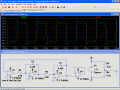
I have some LT1002ACN's around here - they may prove interesting. I already have that circuit in a sim - but it would be good if we can match caps/resistances as closely as possible.
TL072's might be interesting as well, I have a dozen or so of them.
 

Thread Starter

Wendy

Joined Mar 24, 2008
23,415
In for a penny, in for a pound. If they are acceptable to everyone I'll PM Sarge my snail mail address. I don't know these op amps off the top of my head, are they quads?

What's the matter with 741s? I LIKE 741s. I still have some of my first ones, being almost (but not quite) indestructible. :D 30 year old chips aren't that old, are they?

Thinking about it, before we get ahead of ourselves, let me try it with the LM324s first, as a baseline. If they fall within the predictions I think they will then we have somethng to pursue, if not then the theory is busted.
 

Caveman

Joined Apr 15, 2008
471
The LM324 is one of the slowest opamps ever designed (a long time ago).
The oscillator is a "phase-shift" oscillator but it has only two RC circuits instead of the standard of three. The third RC network is the delay of a slow opamp.
Actually, this circuit has another major difference from a phase-shift oscillator. In a phase shift oscillator each of the 3 RC circuits has a phase shift of 60 degrees for a total of 180 degrees at one and only one frequency. The other 180 degrees comes from an inverting opamp stage which generally also provides the gain.

In Bill's circuit, there is the 180 degrees in the first stage, and 90 in each of the other stages for 360. However, this is true at all frequencies. Of course, the second requirement of >1 gain eventually falls off due to the integrators' total -40dB/decade as well as the general roll-off off of the open loop op amp.

Of course, this only applies as long as the circuit stays in the non-clipping range, which it won't due to the >1 gain at low frequencies. Then, the shape of the opamp output as it goes into clipping will select the output frequency or frequencies.
 

Caveman

Joined Apr 15, 2008
471
If they work, they work. Who gives a rip when they were designed or manufactured?
I know the answer: The guy who realized how cheap better ones were after banging his head on his workbench for a week to get his circuit working because they didn't work.:D

Actually, they don't suck that much. Could have to do it discrete...
 

Caveman

Joined Apr 15, 2008
471
I believe this type of oscillator has been patented as the Tow-Thomas configuration.
Don't see Bill's circuit there. All opamps either have local feedback (output to input of same opamp through a passive) or feedback around only two opamps. Bill's circuit has an amp with only feedback around 3 opamps.
 

Thread Starter

Wendy

Joined Mar 24, 2008
23,415
OK, here is the base schematic I will use.


I will design for 1Khz, since that gives us 3 digits minimum, a good check number.

I noticed a dumb math error on the freq calculation, so I updated that.

If f = 1 Khz, and c = .1 uf, then R = 2.5 Kohms

Rounding to 2.4 Kohms, f = 1042 Hz, the predicted frequency.

Here's the clamped circuit...


Thread Starter

Wendy

Joined Mar 24, 2008
23,415
I stayed up way too late writing a GWBASIC program that should show the differences between the sine wave and what this sucker comes out with. The green line is the sine wave, the blue line is X squared function tweaked to fit, which is what I believe its waveform is.


Are we having fun yet?

BTW, I did this with my digital camera, for the life of me I couldn't figure out how to transfer the image to XP, Print Screen didn't do it.
 

SgtWookie

Joined Jul 17, 2007
22,230
Hey Bill,
Just tried the circuit in LTSpice using your 4.7k resistors for a virtual ground and LT1002A opamps. It doesn't work very well! Yes, I do get output, but it's incredibly distorted. Simply adding caps doesn't help a lot.

Do you have a dual bench supply? If not, you can make one out of an old computer ATX-form factor supply pretty cheaply.

Linear Technology's LT1002A are dual precision matched opamps. Nice specs, but at $9/each, not inexpensive.
 

SgtWookie

Joined Jul 17, 2007
22,230
After I changed the circuit from a split 12v supply to +12 and -12 supplies, I performed an FFT on the sinewave output - surprisingly clean sinewave, but centered on 740Hz! (See left attachment)

I then reverted to the virtual ground using the 4.7k resistors and single supply so that you could see the difference in the simulations. (See right attachment)
 

Attachments

Caveman

Joined Apr 15, 2008
471
That's the kind of stuff that I saw with my simulations. If you just change the opamps, you can get completely different results.
 

Thread Starter

Wendy

Joined Mar 24, 2008
23,415
Do me a favor if you can, add the clamping diodes shown in the second schematic and use the single power supply. I could use the 4th op amp as a virtual ground to give it a low impedance ground, I've never run into a case where it made a difference. Why do you think it makes such a difference with the LT1002A op amps?

I'll try to get it done tomorrow, between full load of laundry and a large shopping trip (including the stuff for a house guest) and other stuff it was a full day.
 

Thread Starter

Wendy

Joined Mar 24, 2008
23,415
Those diodes weren't in there, they should flatten the tops off of a waveform and make closer to a square wave. I'm trying to understand why the rail voltage on the SPICE drawing is so weird.
 

SgtWookie

Joined Jul 17, 2007
22,230
Well, that's a simulation - not the real thing! Haven't gotten that fired up yet, still recovering after my spouse "helped" straighten out my 'lectronics room :rolleyes:

I did try the diodes in the simulation, but using the dual supplies. The square waves really got their limits rounded off, which is somewhat to be expected, but not as much as the simulation looked like. I really wasn't very happy with what the rest of the waveforms looked like after being mangled by the simulated diodes, so I decided to experiment with the real things.
 

Caveman

Joined Apr 15, 2008
471
Oh, I misread what was said. I went back and did the same exact sim and got the same results. The non-inverting input of the comparator shows a lot of current (+/-30mA) which doesn't make a lot of sense with the datasheet.
Then I dropped the 4.7k's quite a bit, but saw no difference.

Then, I tried putting the GND node on the negative side of the battery and renamed the resistor divided node Vr. Connected it all up properly, and got completely different waves out. The all railed, but during transition have their appropriate curvatures.
 

Thread Starter

Wendy

Joined Mar 24, 2008
23,415
I notice on the first sim the switching isn't occuring during the zero crossover of the sine wave, which is also odd. You would think that would be a constant.

Something else, the slew rate is so slow it can be seen on that scale (which is why their not switching on the crossover), what's up with that?

I appoximate the switching speed at 100us, which works out to a slew rate of .2V/us, which I have trouble believing. The LM723 has a slew rate of .7/us.
 

Thread Starter

Wendy

Joined Mar 24, 2008
23,415
I just found the datasheet for a LM1002A. If I read this correctly this op amp indeed does have a slew rate of .25V/us (worst case .1V/us). I understand it is ultrastable for DC applications, but for AC that seems a lot slow, or is it just me? I know you guys know this, but for the benefit of outside readers slew rate is not frequency response, although they do have some relation to each other.

http://www.linear.com/pc/downloadDocument.do?navId=H0,C1,C1154,C1009,C1021,P1207,D1239


We could probably clean up the clamping diodes with a smaller input resistor. 10uA feedback is a bit small.
 
Top