 Facebook
 Google
 GitHub
 Linkedin
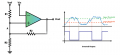
I'm trying to build a circuit to control a contactor that brings online more available power during times of supply droop from our existing source. I decided that an asymmetric inverted Schmitt trigger might do the trick, but am having trouble selecting values for a pretty basic resistor network feeding back into the non-inverting Vref side (for Vupper and Vlower thresholds.)
If for example I wanted a Vref of 24V, a Vupper of 23V and Vlower of 20V, could someone provide formulas for solving for the resistor network (calculating voltage at node A) in the attached graphic? I do not understand how they derived the R.eq of this network in the example I'm referencing.
Thanks,
M
Attachments
-
 30.4 KB Views: 18


