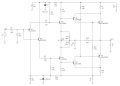
calculating output wattage of class AB amp

MrChips

Joined Oct 2, 2009
35,273
Your 9V battery got warm because the circuit is drawing too much current.
At 6V output the battery energy is practically exhausted.
1661183117141.png

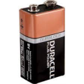
A typical PP3 9V battery has a capacity of about 500mAh and is designed for low power applications such as smoke detectors. Typically, it can supply 50mA for 10 hours. Drawing more than 50mA is anyone's guess as to how long it should last.

Amplifiers are classified into different classes, A, B, C, D, E etc.
Class-A amplifiers are power hogs but are the most linear.
Class-B push-pull amplifiers are more power efficient because only one transistor of the output pair is conducting. It suffers from severe cross-over distortion when one transistor takes over from the other.
Class-AB amplifier is a compromise between class-A and class-B. If you bias the output stage towards class-A you reduce cross-over distortion but draw more current at idle.
If you bias the output stage towards class-B you reduce the current drawn but you have to settle for more cross-over distortion.

Your 9V battery is going dead fast because your DC bias is more towards class-A.
Adjust your DC bias towards class-B and live with a little bit more cross-over distortion.

A PP3 9V battery is not an appropriate power source for a high power audio amplifier.
 

Thread Starter

mike_canada

Joined Feb 21, 2020
239
A typical PP3 9V battery has a capacity of about 500mAh
That explains why in my old design involving the LM386 that the battery lasted only 45 minutes.

Drawing more than 50mA is anyone's guess as to how long it should last.
That's why I stock up on batteries for such an application. Last time I used my previous board for 90 minutes, I had to go through 3 batteries because they were dying. then again, 2 were not brand new to begin with.

If you bias the output stage towards class-A you reduce cross-over distortion but draw more current at idle.
If you bias the output stage towards class-B you reduce the current drawn but you have to settle for more cross-over distortion.
Adjust your DC bias towards class-B and live with a little bit more cross-over distortion.
If I did that, then I won't get max power output to the speaker.

But if the transistors were not heating, where was the current going? I still think there was actually a short.
But in a push-pull amplifier, wouldn't one transistor conduct at a time? otherwise my whole circuit would be blown up by now?
I could guess the speaker but doesn't capacitor block DC?

I replaced the 1.2 ohm resistors with axial ferrite beads (not that that makes a good difference) before I mentioned a warm battery. But don't the 330 ohm resistors connected to the base of the power transistor limit the current?

I did leave the unit on in a steady state with no audio on 9V batteries for about 10 mins so maybe that may have caused a high-speed battery drain.

Today, after the 9V battery decided to almost die, I changed it with 4AA batteries (I know, its not the best for audio), but once I did that, the audio was better (then again the 9V battery must be almost dead). Anyways, I ran the unit on 4AA batteries for about 10 minutes and I didn't notice those batteries being warm.

Perhaps my absolute worst-case scenario for output is that the resistance being delivered to the output speaker capacitor is like 0.1 ohms (from the wiring in the transistors when they are turned on)?

I guess there's never any real win to this for quality audio because quality comes from linear and no emitter resistors give higher watt output which help allow speakers to blast sound farther. And the emitter resistors can counteract that.
 

Thread Starter

mike_canada

Joined Feb 21, 2020
239
volt.jpg

I'm baffled. Someone said I should use emitter resistors but when I measure the emitter currents, they are small. Maybe the power transistors come with resistors built in.

I've seen before amps that use dual-power supplies but why so many transistors? I wonder what happened to the kiss (aka keep-it-simple-stupid) approach.
 

MrAl

Joined Jun 17, 2014
13,859
View attachment 274483

I'm baffled. Someone said I should use emitter resistors but when I measure the emitter currents, they are small. Maybe the power transistors come with resistors built in.

I've seen before amps that use dual-power supplies but why so many transistors? I wonder what happened to the kiss (aka keep-it-simple-stupid) approach.
There is some resistance "built in" to the transistors but not on purpose it's a byproduct of making a transistor.
The reason for the emitter resistor though is to keep the transistor in the linear region, and that means making sure the variation in Beta does not affect the signal for any source of change of that Beta.
For examples, the apparent Beta changes with temperature and collector current and collector emitter voltage. If we allow that stuff to change the gain of the stage, the output gets much more distortion. If we start with a gain of 100 at some point it may go down to 20, which means we have to make sure the transistor is biased in a way that makes that change irrelevant. To get that to happen, the design gain (sometimes called the 'forced' gain) has to be lower than the max gain (100 in this example). The emitter resistor helps to do that, as well as help to swamp the base to emitter voltage change which would also cause distortion because at one point a 1v input would cause a base emitter voltage of 0.65 volts and at 1.1v might cause 0.66 but 1.2v might cause 0.69 volts, and that would be nonlinear and would migrate to the output speaker as harmonic distortion.,
It is not a different story at lower collector currents but it could be less than at higher currents, although the Beta could actually be lower at low current too.

The whole idea is to get as close as possible to an ideal amplifier. An ideal amplifier has perfectly linear operation so any sine wave input comes out as a sine wave output with no additional components. The transistor is incredibly non linear, and so steps have to be taken to make it more linear. The emitter resistor is one way to do this and is present in every linear audio amplifier that uses transistors even if there is a direct feedback from output to input to help with distortion too.

If you dont hear a difference, it could be that you cant hear the difference or that the circuit isnt too linear as it is. At higher output levels though it may be more objectionable.
It doesnt hurt to try different things though and discovery makes it all more interesting.

If you ever get into the calculations behind some of this stuff you will find it incredibly interesting. The transistor is a fascinating device and the math behind some of it brings out the true nature of this amazing invention.
 

MrChips

Joined Oct 2, 2009
35,273
I did not have power transistors to breadboard your circuit.
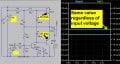
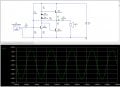
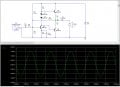
This is a simulation showing negative feedback from the output back to the base of the driver transistor Q1.

When you do your experimentation, adjust R1 and R2 so that the output voltage at [A] is half the supply voltage

AAC CircuitMaker audio amp.jpg
 

Audioguru again

Joined Oct 21, 2019
6,826
The simulator thinks that at 9V I can almost get 2W output power.
Impossible. 2W into 8 ohms is a sinewave that is 4V RMS then (4 squared)/8 ohms= 2W.
A 4V RMS sinewave is 4 x (2 x the root of 2)= 11.3V peak-to-peak then the amplifier needs a supply of 12V to 14V.

Oh, maybe your simulator plays extremely distorted acid rock that is squarewaves. Then with a regulated 9.0V power supply, the amplifier output is 8V peak-to-peak which is 2.83V RMS which produces 1.0W into 8 ohms plus another 1W of distortion= 2W.

You said you measured the weak battery when the tests ended. But you are supposed to measure the battery voltage during the tests.
 

Audioguru again

Joined Oct 21, 2019
6,826
MrChips, your simulation in post #107 has the zero impedance signal source shorting the AC negative feedback from R7, producing no feedback to reduce distortion.
The maximum output swing is low because emitter resistor R4 throws away voltage (use negative feedback from the output instead) and because collector resistor R3 is not bootstrapped.
 

MrAl

Joined Jun 17, 2014
13,859
I did not have power transistors to breadboard your circuit.
This is a simulation showing negative feedback from the output back to the base of the driver transistor Q1.

When you do your experimentation, adjust R1 and R2 so that the output voltage at [A] is half the supply voltage

View attachment 274499
Hey there,

Would you happen to have an LT Spice file for that circuit?
It's a cute little circuit i am tempted to build myself for a cheap little headphone amplifier, but i wanted to test a theory of mine i had since the 1980's which now that i think about it i never tested before.
Thanks in advance.
 

MrChips

Joined Oct 2, 2009
35,273
Hey there,

Would you happen to have an LT Spice file for that circuit?
It's a cute little circuit i am tempted to build myself for a cheap little headphone amplifier, but i wanted to test a theory of mine i had since the 1980's which now that i think about it i never tested before.
Thanks in advance.
Sorry. I don’t have LT Spice. I used CircuitMaker.
 

MrAl

Joined Jun 17, 2014
13,859
MrChips, your simulation in post #107 has the zero impedance signal source shorting the AC negative feedback from R7, producing no feedback to reduce distortion.
The maximum output swing is low because emitter resistor R4 throws away voltage (use negative feedback from the output instead) and because collector resistor R3 is not bootstrapped.
Hello,

That's an interesting observation.
It will actually see some impedance but at higher frequencies it will be worse with lower impedance as the frequency increases and thus the usual 1kHz test for distortion will be misleading because the distortion will increase with frequency.
 

Audioguru again

Joined Oct 21, 2019
6,826
MrChips, it is nice to see fairly low distortion on your amplifier but its voltage gain is low at 2.8 times and its output power when powered from +12VDC is only 0.12W.

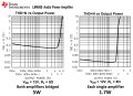
An old little LM4950 IC produces 5W (when bridged) into 8 ohms when powered from +12VDC or 1.7W for each single amplifier.
 

Attachments

MrChips

Joined Oct 2, 2009
35,273
For the benefit of the TS as I pointed out, this is a simple starting point for a classic class-AB amplifier.
Don't expect too much from a 12V supply and non-bridged output.
Q1 is the driver stage to Q2 & Q3 push-pull output stage. For extra gain one can add a preamp stage.

I have tested a similar circuit running off a 9V battery using 2N3904 for Q2 and 2N3906 for Q3.
The sound quality and volume is remarkable. Of note is the fact that I am using a 3" loudspeaker mounted in a solid wooden box.
 

Audioguru again

Joined Oct 21, 2019
6,826
Car radios managed for years.
Class-AB car radios use a 14.4V supply when the 12V battery is charging, a 4 ohm speaker for twice the current of an 8 ohms home speaker, a bridged output that almost doubles the output voltage and current swings and bootstrapping.
15W at low distortion.
 
Top