calculating output wattage of class AB amp

Audioguru again

Joined Oct 21, 2019
6,826
An LM386 amplifier IC is old and cheap. Its output is 6V p-p into 8 ohms when powered from 9VDC. It produces 0.56W into 8 ohms with some distortion or 0.45W with low distortion. Since it is an IC it already is biased for any of its range of supply voltage.
It has a voltage gain of 20 that can simply be increased to 200 by adding a capacitor.

ALL amplifiers have an input coupling capacitor to block any DC input offset voltage.
You talk about your offset voltage but the input coupling capacitor blocks DC. Then maybe you mean the output offset voltage that should be at half the max output voltage swing.

My cheap clock radio produces 0.5W and is plenty loud requiring its volume control to be turned down.
 

Thread Starter

mike_canada

Joined Feb 21, 2020
239
You talk about your offset voltage but the input coupling capacitor blocks DC. Then maybe you mean the output offset voltage that should be at half the max output voltage swing.
So if that means if my voltage source is a constant 9VDC, then the output ideally should be a clean waveform from -4.5V to +4.5V?
 

Audioguru again

Joined Oct 21, 2019
6,826
Battery power is determined by how loud the amplifier plays and what kind of music.
Acid rock played full blast with plenty of clipping uses much more battery power than normal music that has peaks that are almost clipping with the average level of 1/10th. The idle current is also involved in the calculation of battery capacity and length of playing time.

Some battery manufacturers lie about capacity. There are 18650 battery cells made by Name brand companies with a true capacity of 3000mAh. On ebay there are lies from No-Name-Brand companies that say 7700mAh.
 

Thread Starter

mike_canada

Joined Feb 21, 2020
239
fault.png

Ok I found the BIG mistake. In my PCB board I wired the TIP42 and TIP41 in the incorrect places as shown right above this message. How did I determine this? because I remade the circuit while playing with values for input and I actually got audio!
 

MrChips

Joined Oct 2, 2009
35,198
Nope.
You have switched TIP41 and TIP42 and this is wrong.
When I get a chance I will breadboard your circuit.

Or are you saying this is the circuit that gave you no result? No wonder.
If that is the case, just say so. Don’t post the schematics showing your error. That would be very misleading.
 

Audioguru again

Joined Oct 21, 2019
6,826
So if that means if my voltage source is a constant 9VDC, then the output ideally should be a clean waveform from -4.5V to +4.5V?
No, its output does not swing that much. Without emitter resistors, the DC output goes from +1.2V to +8.7V then the output capacitor divides it equally from -3.75V to +3.75V.
 

Thread Starter

mike_canada

Joined Feb 21, 2020
239
No, its output does not swing that much. Without emitter resistors, the DC output goes from +1.2V to +8.7V then the output capacitor divides it equally from -3.75V to +3.75V.
I think I need to drop my output emitter resistor values from 4.7 ohms to 1 ohm. I read somewhere that the resistors are used to prevent thermal runaway (unnecessary Vbe fluctuations) from happening. After last night's tests with 4.7 ohm emitter resistors, the performance of this new amp is somewhat better than the old one I did with the LM386.
 

Audioguru again

Joined Oct 21, 2019
6,826
Thermal runaway is prevented in a powerful amplifier by fastening the diodes to the output transistors.
Your amplifier has flea-power so it will not have thermal runaway.
 

MrAl

Joined Jun 17, 2014
13,809
An LM386 amplifier IC is old and cheap. Its output is 6V p-p into 8 ohms when powered from 9VDC. It produces 0.56W into 8 ohms with some distortion or 0.45W with low distortion. Since it is an IC it already is biased for any of its range of supply voltage.
It has a voltage gain of 20 that can simply be increased to 200 by adding a capacitor.

ALL amplifiers have an input coupling capacitor to block any DC input offset voltage.
You talk about your offset voltage but the input coupling capacitor blocks DC. Then maybe you mean the output offset voltage that should be at half the max output voltage swing.

My cheap clock radio produces 0.5W and is plenty loud requiring its volume control to be turned down.
Hi,

You know how much you hate the LM358 op amp? That's how much i hate the LM386 "audio" "amplifier" chip.
I have to put everything in air quotes because i think the LM386 belongs in only industrial applications not any audio application. Maybe in servos but not audio.
I had several of these chips they are awful.
 

Thread Starter

mike_canada

Joined Feb 21, 2020
239
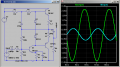
Well I adjusted the parts to match this circuit and I set source voltage to 7 because I was testing things on a 9V battery and the sound is nice for the most part. Here's the funny part. The first say minute of using the battery, I could hear the sound up to 20 feet away then after a while I could hear sound up to about 9 feet away. I think I can get somewhere if I raised the voltage level, but then again all my capacitors are rated for 16V so I wonder if 9V is my safe limit without blowing up a capacitor or is the voltage rating of a capacitor actually the maximum DC voltage allowed through the capacitor (meaning I could use a 16V supply without issue)?wave.png
 

Audioguru again

Joined Oct 21, 2019
6,826
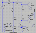
Your circuit is missing a main power supply capacitor.
All capacitors should have a voltage rating at least 1/3rd higher than is used.
The discrete circuit must be re-biased when the supply voltage is changed.

Your 'scope shows that the positive of the output waveform is squashed down to 2.1V peak but the negative is normal at 2.3V peak. That is distortion.
 

Thread Starter

mike_canada

Joined Feb 21, 2020
239
Your circuit is missing a main power supply capacitor.
Damn. I forgot to include that in the diagram. On my real board, I have 2 0.1uF ceramic capacitors. One one each side of the board. I think I'll have to raise those values but my space is rather small for them and my big capacitors are electrolytic.

Maybe I'll just make a separate circuit with a capacitor of a huge uF value ( 1000+uF) that connects to the battery then connect it to my main board via twisted wires.


All capacitors should have a voltage rating at least 1/3rd higher than is used.
I guess that screws up my idea of using 2 7.2V batteries. I guess I'm stuck with a 9V battery because when it comes to replacing the battery, I want to replace it as fast as possible and it would be a pain to pull out and put in a bunch of little batteries to make up for the voltage.

The discrete circuit must be re-biased when the supply voltage is changed.
I do realize this sadly, but it seems that when the audio input resistor is high ( > 6.8K) or when the audio amplitude is small (< 200mV) or when the voltage is 5+, biasing doesn't make much of a difference. I also notice if the voltage is substantially higher (like 12V+), the waveform becomes more natural.

Your 'scope shows that the positive of the output waveform is squashed down to 2.1V peak but the negative is normal at 2.3V peak. That is distortion.
I've had worse when playing with values. I've even seen it where the top was very flat and I've seen it where the bottom part of the waveform was very pointy.
 

Thread Starter

mike_canada

Joined Feb 21, 2020
239
Also, what should I really set the input amplitude to? I will be eventually playing audio from my phone into the circuit. The phone has a volume control. Wikipedia states the typical audio input is 447mV (about 0.9 p-p) But using that high amount creates distorted waves. If I go down to 100mV then I get less distortion and much higher gains. Question is how low could I go with input before sound is so quiet that only a mouse can hear it?
 

Audioguru again

Joined Oct 21, 2019
6,826
The amplifier you are making is very simple and basic. With your low supply voltage its maximum output power without clipping is 0.5W or less. When biased correctly it produces distortion when its output power is above 0.1W.
A good audio amplifier produces very low distortion that cannot be heard at any output level up to clipping.

The sensitivity of our hearing is logarithmic to allow us to hear the very low sound level of a a pin drop to very loud cheers or machines. Then 10 times the power sounds only twice as loud. We can barely notice half or double the power.
 

Audioguru again

Joined Oct 21, 2019
6,826
If your simple amplifier circuit is biased correctly with a 20V supply, then its output voltage swing will be about 18V p-p which is 6.4V RMS. Then its output power into 8 ohms is (6.4V squared)/8 ohms= 5.12W with the distortion it has.

Most modern amplifier circuits are bridged and produce about 3.5 times that power (18W into 8 ohms or about 32W into 4 ohms) and have very low distortion.

Speakers have a good or poor sensitivity and a good or poor frequency response which affect loudness and a decent or awful sound.
 

Thread Starter

mike_canada

Joined Feb 21, 2020
239
Speakers have a good or poor sensitivity and a good or poor frequency response which affect loudness and a decent or awful sound.
I wonder if my speakers are garbage despite them being rated at 4.5W 8 ohm. I bought a handful of them a few years ago when local electronic store Sayal Electronics was selling them on sale for 50 or 75 cents each. The closest match I find on their website is here https://secure.sayal.com/STORE2/View_SHOP.php?SKU=252128 except mine is 4.5W not 2W.

Maybe its time I replace my speakers and even go for higher watt ones
 

BobTPH

Joined Jun 5, 2013
11,659
That speaker is crap and can probably handle 1/2 Watt at most.

Good speakers start at about $30 and you need woofer and tweeter, so about $60 for the drivers and $20 for the crossover. Then you have to put them in a proper enclosure.
 

Audioguru again

Joined Oct 21, 2019
6,826
I bought some Sylvania clock radios at Sayal for $1.75CAN each. I increased the values of a few coupling capacitors and replaced its tiny speaker with one I modded (6.5" woofer and a dome hifi tweeter with a crossover and a port) and it sounds great.

Your tiny speaker is a shrieker producing no bass frequencies and a shriek for high frequencies. It is sensitive only at a few frequencies near 4kHz.
 
Top