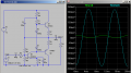
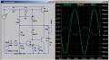
ok so it seems a 10mV offset with 10mV amplitude and same frequency gives a clean signal.
The only mod I did to the real circuit so far was connect the stereo jack (because one pin wasn't connected. I overlooked it). Then when I tried it this time with the audio connected, I heard the same click but when I disconnected the power, I could hear the sound at a super low volume for about a second.
I tried more tests.
I set the volume of the music to max possible now.
When I plug in the battery, I hear the sound but it doesn't seem to be super loud as I expect but its very distorted. I can hear the baseline but the voices are not recognizable (compared to not using my amp circuit).
If I set the music volume level to less than about 80% then I hear no sound. If I set it to about 85%, I be lucky to hear percussion but other sounds I won't be able to hear.
ok i'm re-uploading the file because I forgot to include an emitter resistor and capacitor in parallel and I think my problem lies in that combo. seems 4.7uF in parallel with 100 ohm won't give me enough gain when compared to 470uF in parallel with 100 ohm. I added this combo because I want to achieve better sound but then if I make 100 ohm the wrong value then I won't get the best output.
sorry again. the design is old I forgot to include the 4.7 ohm emitter resistors at the output stage. I'm going to play with the simulator and see what it can do for me. I might have to replace the 4.7 ohms with 1 ohm.
7.2V NiMH fully charged battery but then I would change batteries if one didn't work but for testing purposes the voltage wont exceed 9. As for final design I might go to 14-18V. I have updated the circuit to match the actual one I use and included the asc file (yes I forgot the emitter resistor/capacitor combo along with the emitter resistors when I posted before). I am still curious if 330 ohm resistor pair is too low for tip41c. Somehow, Audioguru doesn't think so as he uses 270 ohm pair.
Ok but I noticed through sim that as I turn the music volume up, the top and bottom of the waveform goes slanted. Is there a way to fix this with a different capacitor and/or resistor value?
Ok but I noticed through sim that as I turn the music volume up, the top and bottom of the waveform goes slanted. Is there a way to fix this with a different capacitor and/or resistor value?
I feel like I need another capacitor somewhere because I want the amp to work across a wide range of voltages. This design so far seems to make the sim happy if the supply voltage is 5+ volts.
So if I used two new brand new fully charged 4000mAh batteries in series on this design to make 14.4V (because my batteries are 7.2V each), will I be able to run this amp with continuous music for at least 6 consecutive hours?
The amplifier must be re-biased if you change the supply voltage.
The output power when biased correctly for a 7.2V supply is a puny 0.47W with high distortion.
For such low power you do not need power transistors at the output.
Your original input signal level was 9 times too high causing squarewaves at the output.
The slant is caused by phase shift that you cannot hear.
I always look at the DC output of an amplifier to see if it is biased so that the output can swing symmetrically.
And I just did that (check output waveform) without looking at the last post. Blue is input waveform and green is output voltage which is amplified. Yellow is current through the load.
So anyways, this is my design for a 6V power source. The problem is this time I hear NO sound regardless of the volume level of the music. Before I changed the 1K input resistor to 6.8K, I heard distorted sound.
Maybe my input voltage level is not correct in the sim. I have it set to 0.25 amplitude but what is it normally for a computer when it blasts audio through the earphone jack at max volume? what is the peak voltage there? Maybe I have to design around that.
Your 6V amplifier is throwing away more than half of its max output signal voltage in the two 4.7 ohms emitter resistors.
All amplifiers have an input volume control but yours has none, then maybe the input level is way too high causing the amplifier to produce severe clipping distortion.
Since the amplifier uses a battery that has its voltage slowly dropping as it is used, then the amplifier should be an IC or have an opamp in it.
Your original amplifier simulation had a completely useless 0.5VDC input offset voltage. The input capacitor blocks that DC.
The amplifier had an extremely low 1k input resistor that shorted away most of the negative feedback producing way too much gain and way too much distortion.
All amplifiers produce severe clipping distortion when the volume control is turned up too high for the voltage gain of the amplifier.
My computer speakers use a 12VDC/1A supply and maybe they are 4 ohms for each output to produce about 3.1W each
with low distortion.
I did one that involved the use of an LM386-1 amplifier but the volume was still too low despite hearing the audio. If I can figure this amp out then I can score something better.
What would you set the input source (DC offset and amplitude) to when diagnosing most amplifiers? because I find that if I make the DC amplitude too high, I get a distorted output. I also noticed if my DC offset is not correct then I get 2 separate waveforms appearing and not crossing each other. I would think the waveforms should cross each other (as the output is inverted compared to the input). right?

 Facebook
 Google
 GitHub
 Linkedin