calculating output wattage of class AB amp

MrChips

Joined Oct 2, 2009
35,299
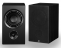
As Bob says, the loudspeaker is only a fraction of the solution. The loudspeaker needs to be in a speaker enclosure to prevent the back wave from cancelling out the front wave.

Your speaker is only 2". You want to start with nothing less than 6-8" diameter.
Even a small computer speaker from a second hand store would make a huge difference.
1660965575155.png
 

Thread Starter

mike_canada

Joined Feb 21, 2020
239
...with one I modded (6.5" woofer and a dome hifi tweeter with a crossover and a port) and it sounds great.
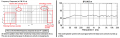
Your tiny speaker is a shrieker producing no bass frequencies and a shriek for high frequencies. It is sensitive only at a few frequencies near 4kHz.
Guess that means I'll need to find better speakers from a flea market or something and put it in a box because average price of at least a somewhat better speaker is $10-$20 each

Had I known this before, I probably would have gotten away with cardboard xmas gift boxes for speaker enclosures but dollarama only sells those kind of boxes around xmas time.
 

Audioguru again

Joined Oct 21, 2019
6,826
A speaker system needs a fair size woofer to play low frequencies and a tweeter to play high frequencies. A crossover network inside the speaker system separates the frequencies to them.
The speaker enclosure must be solid and not vibrate with the speaker sounds (not cardboard).

A neighbor threw out a pair of Sony speakers. They had a 10" woofer and a tweeter.
The woofer produced boomy sounds but no bass and the tweeter produced shrieks and whistles but no high audio frequencies.
Your new speaker also plays sounds extremely poorly like an old telephone:
 

Attachments

BobTPH

Joined Jun 5, 2013
11,677
A good 6.5 in woofer is far better than a crappy 10 in woofer. I built a system a couple of years ago based on a 6.5 in woofer and a 1 in dome tweeter. The box was a ported enclosure about 18 in tall, 13 in wide and 10 in deep.

The box was designed using free software, as was the crossover. They sound far better than anything I have built before. Bass goes down to 40 Hz, and highs are way beyond what my ancient ears can hear. The cost of parts was about what I quoted previously.

But my point is about power. 19 Watts will drive these to ear splitting levels in the 700 square foot room with no audible distortion.
 

MrAl

Joined Jun 17, 2014
13,886
So I guess you're saying the only way an amplifier is decent in sound and sound distance is if its supplied with at least 20+volts?
And dont forget the heatsinks for the transistors.
Probably at least 30% power lost in them, at least 15 watts each.
 

Thread Starter

mike_canada

Joined Feb 21, 2020
239
But my point is about power. 19 Watts will drive these to ear splitting levels in the 700 square foot room with no audible distortion.
I don't know if my speakers are even capable enough to produce sound to people far away, so even if I did reconfigure my circuit to pump out more power, I'd still have to use different speakers as mine are only rated for 4.5W.

And dont forget the heatsinks for the transistors.
Probably at least 30% power lost in them, at least 15 watts each.
With money matters going a bit worse now, Investing in portable 20 volts many times may be a joke. Even buying 3 9V batteries from a store is at least $6+tax. So I might not need heatsinks. Even with my own testing with 9V power, I didn't feel any transistor getting warm. (probably because of Audioguru's theory of my system producing under 2W power and my transistors being rated for 40+W.)
 

Audioguru again

Joined Oct 21, 2019
6,826
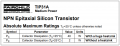
The datasheet for a TIP31 medium power transistor says that its maximum allowed heating power is only 2W without a heatsink.
Its max heating power is 40W with a huge heatsink.

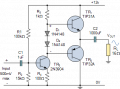
With a 20VDC supply, the simple amplifier produces 5W max into 8 ohms with some distortion. Its 50% efficiency causes the output transistors to produce 2.5W each if the amplifier is playing a continuous tone but much less power and heating with music or speech.
 

Attachments

Thread Starter

mike_canada

Joined Feb 21, 2020
239
In my real circuit I used TIP41 and TIP42, not TIP31. When I look at its datasheet I get the same results for Ta (which is where you saw your 2W). I guess when my budget improves I'll have to invest in higher wattage speakers and possibly transistors with higher wattage ratings.
 

MrChips

Joined Oct 2, 2009
35,299
Your experimental circuit is a minimal class-AB audio amplifier. There are too many deficiencies with such a simple design. You are not going get any significant improvement by making parts substitution.

If you want better performance you need to choose a different route:

1) upgrade the design
2) use an IC power amp
3) switch to class-D audio amplifier
 

Audioguru again

Joined Oct 21, 2019
6,826
The budget is the problem.
Here is Canada the minimum wage is $15.00 per hour. That is $600 per week or $31200 per year. Then money grows on trees.
If money is not thrown away in restaurants, hotels or vacation trips then a good audio system can easily purchased.

I am a Canadian senior and my government pays me and pays for many things for me.
 

Thread Starter

mike_canada

Joined Feb 21, 2020
239
I am a Canadian senior and my government pays me and pays for many things for me.
God I fall through the cracks because I'm not of senior age so government doesn't hand me big money. I also investigated other amp options and they don't seem to help well. I even investigated class D and LM386 amp and I find class AB works far better for me. Looks like I'll play with LTSpice for a long time
 

k1ng 1337

Joined Sep 11, 2020
1,038
You'll not get 100% accurate - the limits of error are too large.
For instance, diode voltage drop = 0.65V±0.1V not only does it vary from type to type, from batch to batch and depend on the current, it also varies with temperature.
Same applies to voltage drop across an emitter follower. For a transistor with low Hfe working at high current it could be as much as 1V, but the generic 0.6V for both diode and emitter follower voltage drops is a good start.
Then there's your battery. It says 9V on it, but it's 10V when it's new and still working at 8V.
Voltage drop across TR3: it says 0.4V for Vce(sat) in the datasheet, but that's at 150mA. No figures for 10mA, but you can be certain that it's NOT zero. Some transistors might manage 10mV, but most don't, unless they are designed for switching, and you need a transistor designed for amplification.

6V is the hypothetical maximum peak output from a 12V supply, because the hypothetical maximum peak-to-peak output is 12V.

@Papabravo 's simulation is not "exact" either, it uses the values for voltage drops contained is SPICE. It's only as accurate as the SPICE models - and they are based on the typical values in the datasheets.
I'm sure he could make SPICE give you minimum and maximum values, calculate the standard deviation and the limits of error if he wanted to; but if the answer is accurate within 1dB (±12%) then audibly no-one will be able to tell. Anyway, it assumes that we all listen to 1kHz sinewaves, not music.
If neither the calculation or simulation are accurate, looks like the only solution is to make him a working prototype! :p
 

BobTPH

Joined Jun 5, 2013
11,677
I meant to say 10 Watts for ear splitting sound. Normal listening level, for me at least, is more like 1-2W. The tiny USB powered class D amp that puts out 1.5W produces way louder sound than I need for my computer soeakers. These are all over EBay for about $1 a piece.
 

Thread Starter

mike_canada

Joined Feb 21, 2020
239
Ok so while inside my budget, I did more experimentation. I deliberately shorted the emitter resistors because I wanted more power. The simulator thinks that at 9V I can almost get 2W output power. I tested things with a 9V battery and I was expecting the transistors to somewhat heat up but instead the 9V battery was warm (neither hot or cold). But it did cool down when I disconnected it. I guess there's a threshold in the battery that it heats when one draws too much current from it that I've apparently exceeded. After tests, I measured the battery with a voltmeter and it reads 6V. Nice news, I can still use it to amplify sound but 9V would be better.
 

Thread Starter

mike_canada

Joined Feb 21, 2020
239
emitter resistors as in the resistors connected between the power transistors emitters and the capacitor that feeds audio to the speaker.
 

MrChips

Joined Oct 2, 2009
35,299
This is a good starting point for a classic class-AB push-pull audio amplifier.
What is missing is negative feedback.

1661180877647.png

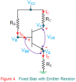
Purpose of emitter resistor

1661180953841.png

The resistor on the emitter leg of the circuit serves two purposes.
1) It limits the maximum current through the transistor, particularly when Rc = 0 in this application.
2) It provides negative feedback.

How does this provide negative feedback?
Emitter current IE increases as VBE rises, i.e. rising positive signal on the base.
VE = IE x RE
Thus VE rises. This has an opposing effect on VBE since VBE = VB - VE.
This lowers the gain of this transistor stage but provides benefits to the circuit.

Negative feedback is desirable
1) It provides DC stabilization and prevents thermal runaway.
2) It reduces non-linearity, i.e. reduces distortion in AC waveform.

There are additional ways of adding negative feedback which I will show in another post.
 
Top