Cable tester to indicate voltage present on conductors

Thread Starter

DSGarcia

Joined May 28, 2008
10
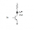
I would like to build a simple battery powered cable tester that will sense and indicate the presence of 4 to 24 VDC on a four conductor cable, with one of the conductors being common. I would like to use three LEDs that will indicate the respective conductors that have a voltage present. I was looking at using something like a ULN2003 or MC1413, but these have inverted outputs and would indicate when the voltage is absent, not present. I would like to use parts that are easy to locate (Mouser Electronics is my primary supplier) so something like a UDN2981 is out of the question. Because this is a tester that will be frequently connected and disconnected from various live cables, I need something that is robust and will be resistant to static discharge, etc.
 

#12

Joined Nov 30, 2010
18,224
You want to measure 3 wires and you are looking at a chip with 7 inverters. Wire it with 2 inverters in series for each measurement to get back to positive logic.
 

Attachments

Thread Starter

DSGarcia

Joined May 28, 2008
10
I found a 2N7008-G MOSFET that has a 30V gate-to-source specification. However, I understand that the gate on a MOSFET is sensitive to static and the effects are cumulative over time. How do I protect the gate since it will be the 'probe' signal on the cable tester?
 

Thread Starter

DSGarcia

Joined May 28, 2008
10
You want to measure 3 wires and you are looking at a chip with 7 inverters. Wire it with 2 inverters in series for each measurement to get back to positive logic.
I had looked at that device, but since it sinks the current, I am unsure how to connect two drivers in series.
 

Thread Starter

DSGarcia

Joined May 28, 2008
10
#12, Thanks for the advice, but I am not too educated on selection and use of transistors. I would need to know the part number to use plus what value resistor to use on the base of the transistor plus any biasing that needs to be done if any. I had suggested the MOSFET, but I am concerned about damage to the gate since I don't know how to protect that from potential damage. Thinking about the ULN2003 solution, which is a cheap and robust part, would I perhaps put a pull-down resistor at the input of the first driver and a pull-up resistor at the output of the first and connect that output in series to the input of the second driver? Perhaps 10K ohms?
 

Thread Starter

DSGarcia

Joined May 28, 2008
10
No, Thinking about it some more, I don't think that is how I would connect the two in series. I am still a bit confused.
 

Thread Starter

DSGarcia

Joined May 28, 2008
10
Does this make sense to you?
You should ground pins 4,5,6, and 7
I can't say that I understand how the inputs work with this circuit, but as long as when the input is floating or is zero volts, the corresponding LED is off and whenever there is 4-24VDC at the input, the corresponding LED is on, that's what I need.
Thanks for the help. I'll try it out and see what it does.
 

#12

Joined Nov 30, 2010
18,224
I can't say that I understand how the inputs work with this circuit,
Connect one of the wires you are testing to each of the inputs. 3 wires, 3 inputs.
Connect the ground of your wiring circuit to the ground of the detector circuit.
If voltage, then light.
 

Thread Starter

DSGarcia

Joined May 28, 2008
10
Connect one of the wires you are testing to each of the inputs. 3 wires, 3 inputs.
Connect the ground of your wiring circuit to the ground of the detector circuit.
If voltage, then light.
I understood that I connect the inputs to the cable conductors to be tested. What I didn't understand about the inputs was the purpose of the zener diode & resistor on each input. I breadboarded the circuit today and the LED was quite dim (with a 9VDC input signal). It was less dim if I took out the zener. If I take out the resistor also, the LED is as bright as it should be. I added pull-down resistors on the inputs so the input wouldn't be floating and that seems to be working fine. I am still curious about the purpose of the zener/resistor combination and was wondering if it simply needs a little tweaking.
 

#12

Joined Nov 30, 2010
18,224
According to the datasheet of the chip it only needs 10 microamps to send 10 ma through the LED. The threshold voltage for the chip is about 1.2 volts and if the input voltage stops at 3.3 volts, that makes 2.1 volts/100k = 21 microamps to the input. Apparently that isn't enough so you can reduce the input resistor to 10k if you want to try that.
Then you say this:
I need something that is robust and will be resistant to static discharge, etc.
That is what the input resistor and the zener diode are for...to avoid static discharge from hurting the chip.
I took out the zener. If I take out the resistor also, the LED is as bright as it should be.
You asked for it. I provided it. You promptly discarded it.
 

Thread Starter

DSGarcia

Joined May 28, 2008
10
According to the datasheet of the chip it only needs 10 microamps to send 10 ma through the LED. The threshold voltage for the chip is about 1.2 volts and if the input voltage stops at 3.3 volts, that makes 2.1 volts/100k = 21 microamps to the input. Apparently that isn't enough so you can reduce the input resistor to 10k if you want to try that.
Then you say this:

That is what the input resistor and the zener diode are for...to avoid static discharge from hurting the chip.

You asked for it. I provided it. You promptly discarded it.
I appreciate your help; I really do. The only reason I "discarded" your advice is because it didn't work and I don't know enough to understand the protection circuit and adjust component values. I didn't mean to offend you, it simply didn't work as you specified it. The LEDs I am using draw 20mA at around 3.5 VDC (depending on the LED color). Perhaps a 10K resistor as you suggest will do the trick. I will try that to see if it helps. Again, thanks for your advice.
 

Thread Starter

DSGarcia

Joined May 28, 2008
10
The LEDs I designed for are Red. They need 2.2 volts and they use 10 ma. You changed every specification which I provided and then claimed the circuit didn't work. Go figure.
Sorry you feel that way. I didn't mean to offend you. I did not change the specifications. I did not provide the LED spe
 

Thread Starter

DSGarcia

Joined May 28, 2008
10
#12,
I put two 100K resistors in parallel on the breadboard and that worked. I will order 50K resistors to build the testers. Sorry for the misunderstanding. I had already specified the LEDs in my mind because I needed panel mount LEDs bright enough to use outside. I'm also using different colors to indicate which conductor is 'hot. I knew how to calculate the resistance and was really looking for the circuit to turn them on and off. I didn't pay too much attention to that part of your circuit and didn't provide every last detail because I felt I already had that part of the circuit covered. I had originally misunderstood the ULN2003 and had my logic inverted but I knew that the part could sink more than enough current for my needs. As I said, I didn't understand the protection part of your circuit which is what I really needed. I also didn't understand that it was critically limiting the amount of current that the part could sink. Again, thanks for your patience and assistance. This will be a great help.
 
Top