BYPASSING THE FUNCTIONS OF A TREADMILL.

Thread Starter

sharpteeth

Joined Feb 7, 2025
10
Hello again. I'm an artist with limited electrical knowledge. (But learning!).

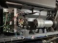
I was looking to have a treadmill run on a just a switch and maybe some sort of dimmer to control the speed. I'd like to bypass all of the functions.

#1- What power adapter specs would I need to use for the set up below?

#2- What type of dimmer switch (if it's even called that) could be used to control the speed? If not possible maybe just an on/off switch.

#3- If this motor can't be slowed down or sped up what is it's standard speed?

#4- How would I wire it up? I assume the power is connected to the black & red wires but not sure what is anything is needed to attach tot he blue ones.

THANK YOU.IMG_0965.JPGIMG_0966.JPGIMG_0965.JPGIMG_0968.JPG
 

MaxHeadRoom

Joined Jul 18, 2013
30,559
Appears to be a version of the MC2100? Does the board show this, if so there is a reverse engineered schematic on the site here.
It uses 20hz PWM to control it, there are some PWM units out there that will run it,
I made some up with a 8 pin micro with stop-start PB's. for these boards.
It is just an input to header HD2
The board has built in soft start and does not need anything else apart from the MC2100 board. and 20hz controller.
 

Thread Starter

sharpteeth

Joined Feb 7, 2025
10
Appears to be a version of the MC2100? Does the board show this, if so there is a reverse engineered schematic on the site here.
It uses 20hz PWM to control it, there are some PWM units out there that will run it,
I made some up with a 8 pin micro with stop-start PB's. for these boards.
It is just an input to header HD2
The board has built in soft start and does not need anything else apart from the MC2100 board. and 20hz controller.
Yes the board says MCL2100-LS-30

This is probably outside of my brain capacity but can you send me the link to the reverse engineered schematic on the site?

Is this the type of device you are suggesting can control it?

https://www.amazon.com/dp/B071NQ5G7..._sms_apin_dp_ABCTDHBH1V7JSWSSQ9MP&starsLeft=1
 

Thread Starter

sharpteeth

Joined Feb 7, 2025
10
This is one, mine does not have the slick case !
https://el34world.com/Misc/Cnc/TreadmillMotor1.htm
This is amazing. And if you're the one who made that can crusher bravo man. Good reason to create empty cans if u know what I mean.

I'll look this over and check back if I have any other questions. But definitely added wind to my sails. Thank you.

If you are so inclined I have a more intricate project I am trying to solve here:
https://forum.allaboutcircuits.com/...e-these-two-devices-help.205327/#post-1966386
 

Thread Starter

sharpteeth

Joined Feb 7, 2025
10
Would it be possible for someone to let me know how to wire this device to the treadmill? I want to be able to bypass all the special functions and simply turn it on and control the speed for an art project. I would greatly appreciate the help in layman's terms... Thank you.


IMG_1081.JPG


IMG_0968 copy.jpg
 

Attachments

MaxHeadRoom

Joined Jul 18, 2013
30,559
Use the reverse engineered print posted in the forum as a reference :
The freq gen has to be set to exactly 20hz and input to HD2 pins 1 & 4
Otherwise The motor and power leads are all that is required to the board..
BTW the input goes through an Opto, and the series resistor is very low, so in some cases a series resistor has to be added in series with pin 4, trace the resistor out and check it.
If you also have the CB (circuit breaker) terminals, that is needed also.
 
Last edited:

Thread Starter

sharpteeth

Joined Feb 7, 2025
10
Use the reverse engineered print posted in the forum as a reference :
The freq gen has to be set to exactly 20hz and input to HD2 pins 1 & 4
Otherwise The motor and power leads are all that is required to the board..
BTW the input goes through an Opto, and the series resistor is very low, so in some cases a series resistor has to be added in series with pin 4, trace the resistor out and check it.
If you also have the CB (circuit breaker) terminals, that is needed also.
Keeping in line with your Einstein quote-- "Imagination is more important than knowledge....". I can say that I only understand bit of what you've explained. I have the imagination part down-- the knowledge is the problem and time is not on my side.

Can you tell me clearly which wires go into the V- V+ and which wires in the PWM ports? You said "the motor and power leads are all that is required to the board" Are you talking about two blue wires from the motor?

As you can see I'm feeling around in the dark here. It' must be frustrating for you because this seems clear but I do appreciate your patience. This art project is a bit ambitious with these electrical aspects but once I have this running I can concentrate on what's more in my wheel house.

Happy to make a donation to your venmo etc for a quick easy drawing of how to wire this up--

Thank you
 

MisterBill2

Joined Jan 23, 2018
27,180
The TS needs to understand that if the controls are by passed then every one of the safety features are also bypassed. That includes those intended to avoid damage when something jams.
 

MaxHeadRoom

Joined Jul 18, 2013
30,559
Can you tell me clearly which wires go into the V- V+ and which wires in the PWM ports? You said "the motor and power leads are all that is required to the board" Are you talking about two blue wires from the motor?
As you can see I'm feeling around in the dark here. It' must be frustrating for you because this seems clear but I do appreciate your patience. This art project is a bit ambitious with these electrical aspects but once I have this running I can concentrate on what's more in my wheel house.
Happy to make a donation to your venmo etc for a quick easy drawing of how to wire this up--
Thank you
The motor PWR leads go to the same pair, V+ V-.
The PWR is the same pair AC-IN . and CB1 CB2 are the same.
Tomorrow Tuesday I can draw up the connections if needed.
BTW. if the motor is overloaded, a current limit kicks in plus other things like ramp up, there is also a processor on the motor board for monitoring RPM etc.
 

MaxHeadRoom

Joined Jul 18, 2013
30,559
"Very Confusing"??
Not really, these MC2100 style boards are used as stand alone motor controllers , just require a 20Hz PWM signal to control them, I made up a small, 50mm square 8 pin Picmicro board that does it, complete with PB stop & Start.

@sharpteeth , Will post diag shortly.
 

MaxHeadRoom

Joined Jul 18, 2013
30,559
Hopefully this shows it, you need to check the current going to the Opto input pin 1 of the 837 4 pin opto as the series resistor is very low, and depends on the one in the external generator unit that provides the 20Hz PWM.
Cannot be over 50mA.
Input signal is HD2 pin 1 & pin 4.
LED on board should be on at power up, and steady flash when recognizing a valid signal


1739900581964.png
 

MaxHeadRoom

Joined Jul 18, 2013
30,559
But fairly simple & straight forward.:confused:
All of the connections shown already exist just have to be removed together with the main board
 
Top