
 Facebook
 Google
 GitHub
 Linkedin
im close to starting my circuit making for my final GCSE project in systems and control
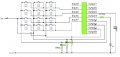
and i need help, i have my basic circuit for my design with a keypad LED, PICAXE and a piezo sounder, the system will sound an alarm when a connection between a reed switch is broken and not stop untill the 4 digit code is entered, this code will then show up in an LCD screen
but now i need help, first problem:
I need to use and LCD screen bu i dont know how i would go about attaching one, i think i have an i dea but im not entirely sure, would i connect a pin from the pic chip to the data pin on a shift register then a pin to the data clock then from the S/R to the R/S, D0 and D1 of the lcd screen and one from he pic straight to the LCD like in the link below? but then for his i would need o alter my design for a a bigger pic chip
http://www.rentron.com/Myke1.htm
or would i go about it a different way?
Second Problem:
I need also to connect a reed switch is this as simple as any other switch? if so what resistor would i use? wold i just connect to a pin on the pic hip then to the positive rail with a 10kΩ resistor? or smaller?
Third Problem:
I would then also need to make a flow chart for my system but making them is not my strong point so could some one 'point me in the right direction' so to say?
and i need help, i have my basic circuit for my design with a keypad LED, PICAXE and a piezo sounder, the system will sound an alarm when a connection between a reed switch is broken and not stop untill the 4 digit code is entered, this code will then show up in an LCD screen
but now i need help, first problem:
I need to use and LCD screen bu i dont know how i would go about attaching one, i think i have an i dea but im not entirely sure, would i connect a pin from the pic chip to the data pin on a shift register then a pin to the data clock then from the S/R to the R/S, D0 and D1 of the lcd screen and one from he pic straight to the LCD like in the link below? but then for his i would need o alter my design for a a bigger pic chip
http://www.rentron.com/Myke1.htm
or would i go about it a different way?
Second Problem:
I need also to connect a reed switch is this as simple as any other switch? if so what resistor would i use? wold i just connect to a pin on the pic hip then to the positive rail with a 10kΩ resistor? or smaller?
Third Problem:
I would then also need to make a flow chart for my system but making them is not my strong point so could some one 'point me in the right direction' so to say?






