Building a TV lift cabinet, need help selecting components

Thread Starter

fallingcow

Joined Dec 4, 2018
5
I'm building a TV lift cabinet. The lifting comes from a scissor lift powered by a drill. It needs to turn on when the TV turns on, drive up to a switch, turn off, and reverse the current so it can come back down when the TV turns off. I want it to work completely independently; ie: no extra buttons or remotes.

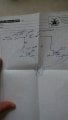
My electrical experience is pretty limited, but this doesn't sound that hard. I attached a basic wiring diagram a friend helped me mock up.

My problem is I don't know what I actually need to buy, or where to get it. Also, instead of a manual switch at the top of the diagram I want it to work off when the TV has current or not. I assume that's another relay of some kind.

So assuming you all agree the diagram makes sense, please tell me if it doesn't, what I really need is the names of these specific components and a recommendation of where to buy them. Turns out if you just type "limit switch" into Google you get more results than are helpful.

Thanks for anything you can help with.
 

Attachments

Thread Starter

fallingcow

Joined Dec 4, 2018
5
Thanks. I actually read that thread before posting and I didn't see what I was looking for. It was a more of a problem solving exercise, where mine is more of a product recommendation. I'll read it again, though. Maybe I missed something.
 

ericgibbs

Joined Jan 29, 2010
18,766
hi,
I brought it to your attention so that it may have suggested alternatives.
I am sure there many members who have experience of this type of product and will post options.
If you post your location you should get help identifying suppliers in your area.
E
 

LesJones

Joined Jan 8, 2017
4,174
Just some questions to star with.
1 Is raising the TV initiated by a switch (External to the TV) or by sensing that the TV has been switched on with it's own remote control. If it is in the down position I don't see how the TV can see the IR signal from it's remote to turn it on.
2 The drill motor seems to be powered from 120 volts Am I correct in assuming that this is the AC mains supply. If this is so you can't reverse the motor in a mains powered drill by swapping over the mains wires. I have only seen mains drills use a series wound motors which need the polarity relationship between the field and armature reversing. Have you considered using a battery powerd drill (Using a DC supply rather than it's own battery.) Other than quite recent ones that have brushless motors they are almost allways permanent magnet motors that can be reversed by reversing the polarity.
3 What I assume in your drawing are relays seem to be supplying power to the motor. The output of a relay is only a set of contacts (Or more than one contact.) that can switch a power source to a load.

Les.
 

Thread Starter

fallingcow

Joined Dec 4, 2018
5
Thanks for the reply

1. When the TV is down there will be two ways to turn it on. First, the PS4 can turn it on through HDMI. Second, I have an IR repeater so the remote will still work.
2. The drill I'm planning to use is a corded 120v drill. Correct. Hmm. So, how does the direction switch on the drill work? I mean, they can switch directions. There has to be a way to do that. I could maybe use a battery powered drill modified to run off the mains, but a battery would need changing and the stand will be pretty heavy.
3. I'm not sure I've completely understood this question, but that sounds like my understanding.

MOD: Cleaned up your image.E

IMG_20181204_130047.jpg
 
Last edited by a moderator:

LesJones

Joined Jan 8, 2017
4,174
1 So you need to sense that the TV is switched on. You could sense current in the power feed to the TV using a small current transformer with it's output driving the base of a transistor via a bridge rectifier. The transistor would drive a relay. You could have a suitable value resistor in series with the power to the TV such that there was about 3 volts drop across the resistor. Use that 3 volts (AC) via a current limiting resistor to an opto coupler that is designed for AC input. (Or use a standard opto coupler with a bridge rectifier.) The output would drive a relay via a transistor. One simple way that MIGHT work if the TV has a USB socket and the socket is NOT powered when the TV is in standby mode is to use the 5 volts from the USB socket to drive a relay.

2 The direction switch in the drill reverses the polarity of the armature with respect to the field coils, So if you used a DPDT relay for reversing it would be connected between the field coils and the armature.

3 You are using very stange symbols for the relays. I am assuming the two connections on the left are the coil and the two connections on the right are a single normally open contact. You seem to be switching the coils with 120 V AC (Which is fine.) But the contacts just seem to short out the motor and mains supply. I suggest that you use relay symbols that others understand such is in the schematics I posted in the thread that ericgibbs linked to in post #2

Les.
 

Thread Starter

fallingcow

Joined Dec 4, 2018
5
There's a lot of things I need to research here. It will take me a while to get a handle on it. But I have specific things to Google so that's very helpful.

While I'm doing that does anyone have a suggestion on where to buy components? There aren't any electronics stores near me, but a good online supplier would be great.
 

LesJones

Joined Jan 8, 2017
4,174
I think the first thing you need to establish is the way the reversing is done on the particular drill that you plan to use. Most series wound motors I have seen have one field coil either side of the armature so that their inductance helps to filter out RF interference getting back into the mains. It is also possible that both field coils are in series on one side of the armature. In both of these cases the reversing relay (DPDT) would reverse the connections to the armature. A third (Remote) possibility that I have only seen recently (On the ETO forum.) is two field windings with reverse polarity connected to one side of the armature and the direction is selected by which of the two field windings the power is connected to. This would only need a SPDT relay to reverse the motor.
I agree with crutschow that asking about supplier is poinless when you have not even said which country you are in. Also in your profile you list your accupation as "Maker" I don't know what that is so it is difficult to get a feeling for your level of electrical / electronic knowledge which changes the the way I answer questions. I dont know how basic I need to make explanations.

Les.
 
Top