Facebook
 Google
 GitHub
 Linkedin

Hello everyone.
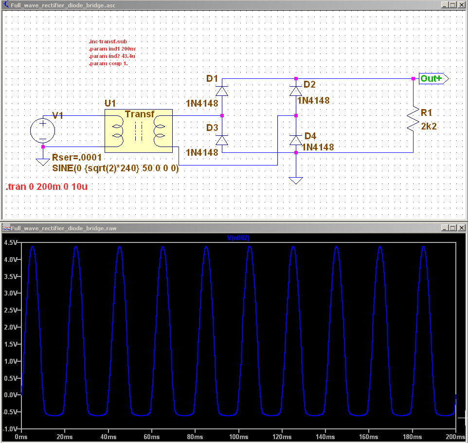
I will be working a bit with transformers in the next 3 months or so in school. And I was looking to build a symbol/model/subcircuit that I could use every time I need to use a transformer instead of building one every time I need one.
So, usually I use 2 inductors and a 'K' parameter and some simple math to find the relative inductances to produce the desired output voltage.
What I want is just add that Transformer symbol, insert L1, L2 parameter values, the coupling factor and nothing else to have my transformer ready to use.
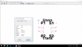
But I don't know many aspects of how to build a symbol/model/subcircuit. So I was about to try the follwoing:
- Open an 'ind.asy' symbol file in LTSpice.
- Duplicate, mirror and position the first inductor to have a second inductor that will act as the secondary winding.
- Add L1 and L2 in curly brackets to be able to change their values according to the ratio between windings. Same with 'K' parameter.
But then, questions starts.
As I duplicate the 1st inductor, 'L' parameter is not duplicated. So, when I use this symbol, how am I going to set L2 value?
Also, when I use this symbol, as I don't have an L2 parameter, how am I going to associate K to L1 and L2?
I will be working a bit with transformers in the next 3 months or so in school. And I was looking to build a symbol/model/subcircuit that I could use every time I need to use a transformer instead of building one every time I need one.
So, usually I use 2 inductors and a 'K' parameter and some simple math to find the relative inductances to produce the desired output voltage.
What I want is just add that Transformer symbol, insert L1, L2 parameter values, the coupling factor and nothing else to have my transformer ready to use.
But I don't know many aspects of how to build a symbol/model/subcircuit. So I was about to try the follwoing:
- Open an 'ind.asy' symbol file in LTSpice.
- Duplicate, mirror and position the first inductor to have a second inductor that will act as the secondary winding.
- Add L1 and L2 in curly brackets to be able to change their values according to the ratio between windings. Same with 'K' parameter.
But then, questions starts.
As I duplicate the 1st inductor, 'L' parameter is not duplicated. So, when I use this symbol, how am I going to set L2 value?
Also, when I use this symbol, as I don't have an L2 parameter, how am I going to associate K to L1 and L2?