I have a solar panel battery charger project, but have issues with the voltage dropping from the output of the buck converter (LM22680).
Setup:
Bench power supply primarily set to 12V. Current limit set to 100mA. Used as PWR_IN
J105 Shunted
Observations:
1) With no load (J108 left open), the output of the LM22680 is a clean output voltage
2) With a 1k resistor as a load, the output of the LM22680 is a clean output voltage
3) Connecting the output from LM22680 to the battery charging chip (LTC4055) via J108, the output from the LM22680 drops (~0.7 - 1.2V) depending on the input voltage.
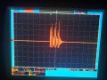
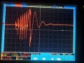
- If PWR_IN is set to 12V, the mean voltage on VIN_+5V is ~3.044V with a current draw of ~8mA ( Waveform #001 )
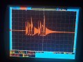
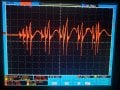
- If PWR_IN is set to 8V, the mean voltage on VIN_+5V is ~4.168V with a current draw of ~16mA ( Waveform #002 )
4) LEDs D107, D108 (CHRG, ACPR) flicker ON/OFF even though the voltage on WALL is set above the threshold voltage of 1V. I've changed resistors R111, R112 so that the voltage on this pin is ~3V so that any drop in voltage on VIN_+5V will still keep the LTC4055 ON and Charging. But it doesn't seem to work.
5) Bypassing the buck converter circuit and applying voltage to the LTC4055 (J108, pin 2) through the Benchtop power supply (5V), the battery charging circuit works fine and the voltages are stable.
Questions:
1) I've set the output voltage for the LM22680 to be ~5V (via R102, R103), why does the output voltage from LM22680 change drastically depending on the power supply input, even though it is well above the set output voltage of ~5V? Is this an efficiency issue? A chip conflict issue with the LTC4055 chip switching ON/OFF?
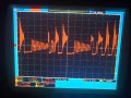
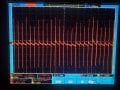
2) Why is there a pulse (noise) every ~1ms? Is this normal for buck converters under load?
3) How can I cleanup the VIN_+5V voltage signal? Adding a 1000uF or 4700uF polycap didn't seem to have any effect
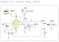
Schematic in attachments
Waveform #001

Waveform #002

Setup:
Bench power supply primarily set to 12V. Current limit set to 100mA. Used as PWR_IN
J105 Shunted
Observations:
1) With no load (J108 left open), the output of the LM22680 is a clean output voltage
2) With a 1k resistor as a load, the output of the LM22680 is a clean output voltage
3) Connecting the output from LM22680 to the battery charging chip (LTC4055) via J108, the output from the LM22680 drops (~0.7 - 1.2V) depending on the input voltage.
- If PWR_IN is set to 12V, the mean voltage on VIN_+5V is ~3.044V with a current draw of ~8mA ( Waveform #001 )
- If PWR_IN is set to 8V, the mean voltage on VIN_+5V is ~4.168V with a current draw of ~16mA ( Waveform #002 )
4) LEDs D107, D108 (CHRG, ACPR) flicker ON/OFF even though the voltage on WALL is set above the threshold voltage of 1V. I've changed resistors R111, R112 so that the voltage on this pin is ~3V so that any drop in voltage on VIN_+5V will still keep the LTC4055 ON and Charging. But it doesn't seem to work.
5) Bypassing the buck converter circuit and applying voltage to the LTC4055 (J108, pin 2) through the Benchtop power supply (5V), the battery charging circuit works fine and the voltages are stable.
Questions:
1) I've set the output voltage for the LM22680 to be ~5V (via R102, R103), why does the output voltage from LM22680 change drastically depending on the power supply input, even though it is well above the set output voltage of ~5V? Is this an efficiency issue? A chip conflict issue with the LTC4055 chip switching ON/OFF?
2) Why is there a pulse (noise) every ~1ms? Is this normal for buck converters under load?
3) How can I cleanup the VIN_+5V voltage signal? Adding a 1000uF or 4700uF polycap didn't seem to have any effect
Schematic in attachments
Waveform #001
Waveform #002
Attachments
-
 77.9 KB Views: 14
 -
 121.7 KB Views: 13