Buck converter on Aluminum PCB (not working)

Status
Not open for further replies.

Thread Starter

Mark Ariel Livelo

Joined Feb 20, 2018
6
Hey there, we are trying to design a pcb layout for led light with buck converter components around it on aluminum PCB for LED heat transfer purposes.
Unfortunately it is not working after several troubleshoots. I tried to isolate the problem by transferring again the components to FR4 PCB and put the LED separate on aluminum PCB and it worked.

What are your thoughts on this failure test?
 

MisterBill2

Joined Jan 23, 2018
27,744
What is the aluminum substrate connected to?
I never heard of an aluminum PC board, and so I am wondering how any part of the circuit is not connected directly to the board. Also, aluminum is hard to solder to, and so that may be another portion of your problem.
 

ebp

Joined Feb 8, 2018
2,332
Aluminum substrate is very popular for LED boards because of its excellent thermal conductivity. It is essentially rather like a flexible PCB, with copper conductors, bonded to aluminum. Typically the circuitry is single-side surface mount.

Normally the aluminum is not part of the circuitry, which I suspect is the problem - it simply ties everything together with capacitance, Of course ground plane conventional PCBs would do the same, except the plane is, well ... ground (or a power plane at ground potential to AC due to decoupling). Without grounding the substrate the capacitance will do things like couple fast edges from power parts of the circuit to sensitive nodes like error amp inputs. LED drivers often switch moderately high voltage to run long series strings of LEDs. Slew 30 or 40 volts in a few nanoseconds and you can put some substantial current into that unwanted array of coupling capacitors.
 

MisterBill2

Joined Jan 23, 2018
27,744
Aluminum substrate is very popular for LED boards because of its excellent thermal conductivity. It is essentially rather like a flexible PCB, with copper conductors, bonded to aluminum. Typically the circuitry is single-side surface mount.

Normally the aluminum is not part of the circuitry, which I suspect is the problem - it simply ties everything together with capacitance, Of course ground plane conventional PCBs would do the same, except the plane is, well ... ground (or a power plane at ground potential to AC due to decoupling). Without grounding the substrate the capacitance will do things like couple fast edges from power parts of the circuit to sensitive nodes like error amp inputs. LED drivers often switch moderately high voltage to run long series strings of LEDs. Slew 30 or 40 volts in a few nanoseconds and you can put some substantial current into that unwanted array of coupling capacitors.
I am guessing that it can also couple very directly if the soldering is not done right. Or if thru-holes have too much solder in them. So I am suspecting short circuits. AND, of course, a buck-mode switching regulator demands very close control of the signal and power connections.
AND, thanks for the explanation.
 

Thread Starter

Mark Ariel Livelo

Joined Feb 20, 2018
6
Aluminum substrate is very popular for LED boards because of its excellent thermal conductivity. It is essentially rather like a flexible PCB, with copper conductors, bonded to aluminum. Typically the circuitry is single-side surface mount.

Normally the aluminum is not part of the circuitry, which I suspect is the problem - it simply ties everything together with capacitance, Of course ground plane conventional PCBs would do the same, except the plane is, well ... ground (or a power plane at ground potential to AC due to decoupling). Without grounding the substrate the capacitance will do things like couple fast edges from power parts of the circuit to sensitive nodes like error amp inputs. LED drivers often switch moderately high voltage to run long series strings of LEDs. Slew 30 or 40 volts in a few nanoseconds and you can put some substantial current into that unwanted array of coupling capacitors.
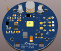
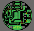
Here is the attached PCB layout, 3d and schematic, @ebp you mean, i should connect the ground to the aluminum substrate to suppress the capacitance?

Moderator's note: Schematic removed from post. Do not re-post.
 

Attachments

Last edited by a moderator:

Thread Starter

Mark Ariel Livelo

Joined Feb 20, 2018
6
One more question: since buck is not isolated to AC mains, there is a tendency that the high voltage would surpass through the aluminum substrate so it would make it dangerous from the high voltage, right?
 

ebp

Joined Feb 8, 2018
2,332
Yes, in a non-isolated converter it does became a safety issue.

There is some possibility that connecting the aluminum to circuit ground using a "Y1" capacitor would work, and if that capacitor is low enough in value it will meet many safety regulations. Y1 capacitors are "double insulated" - the internal structure is designed so that there must be faults in two insulating layers to short circuit the terminals.
 

DickCappels

Joined Aug 21, 2008
10,661
Non-isolated circuits are permitted except those that power LEDs.

From the User Agreement (referenced in the Terms of Service):
  1. Restricted topics. The following topics are regularly raised however are considered "off-topic" at all times and will result in Your thread being closed without question:
    • Any kind of over-unity devices and systems
    • Devices designed to electrocute or shock another person
    • LEDs to mains
    • Any kind of jammers (ie - Phone jammers)
    • Rail guns and high-energy projectile devices
    • Transformer-less power supplies
    If You come across a thread or post discussing any of the above topics please report the thread so We can close, and if necessary remove, the offending thread/posts.
 
Status
Not open for further replies.
Top