Facebook
 Google
 GitHub
 Linkedin
Hey everyone,
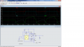
I decided to make my own buck converter using an Atmel 328au uC, NCP5901 MOSFET gate driver, and an op amp for current feedback (which I am not using currently). I attached two images, one of the board layout and one of an oscilloscope image of the voltage at the gate (CH1) and the voltage at the source (CH2). Vin is = 12V so I expected the bootstrap capacitor to be close to 24V - some losses. Both oscilloscope images are referenced to GND. I'm sure there are a lot of mistakes here but this is my learning process, haven't done too many designs so far. What may be the reason the board is not operating as I had intended? Also I have many other oscilloscope images at various test points but I don't know which ones I should post.
Thank you for your time,
Stephen