Buck Converter For Atmega328P-AU

Thread Starter

s200bym

Joined Aug 9, 2017
82
Hi All,

I'm making a custom exhaust valve controller and it's going to power an Atmel ATmega 328P-AU chip at 5v, basically, a custom built Arduino.

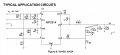
I want to use a buck converter based on the MP2314 chip due to its input range. I don't want the 328p resetting due to power fluctuations and current draws when starting the car and when high load ancillaries are turned on.

I have come up with the schematic below which I found on the MP2314 Datasheet https://docs-emea.rs-online.com/webdocs/14b8/0900766b814b8212.pdf. All caps are ceramic.

Is this a good enough design for what I want?

Mike.


Attachments

DickCappels

Joined Aug 21, 2008
10,661
Quickly eye-balling the schematic, yes, it looks like a buck converter and maybe much more than what you need, especially in an automotive application where saving the odd milliwatt might not be very important. If you want to use this buck converter for the experience you have chosen a good chip but the circuit can deliver hundreds of times the current that your controller itself will draw.

An ATMEGA328 doesn't draw much current, even at its maximum clock rate. You might be way better off using a linear regulator like the LM7805 or LM78L05. Just a thought. To assure that the controller will reset when the engine starts because of a dip in the power supply the regulator can be preceded by a diode in series with the power supply and a large capacitor to ground, ahead of the regulator.
 

dendad

Joined Feb 20, 2016
4,639
I think you need to pull pin 6 high, with a 100K resistor. So, the GND connection shown on your circuit there needs to be removed.
I've not used these chips myself. My choice is just to have a Recom R-78 series
or Tracopower .. https://au.element14.com/tracopower/tsr-1-2450/converter-dc-dc-5v-1a-sip/dp/1696320
These I've used in my products for some years now. It is easier than designing a power supply. I'm getting lazy in my old age ;)
 

Thread Starter

s200bym

Joined Aug 9, 2017
82
Thanks guys, I'll look into the linear regulators.

@dendad looking on the datasheet schematic and having a look at other schematics online, if I'm reading them correctly they all show it the way I have wired it up.

here is the schematic from the MP2314 Datasheet


And here are the pictures of my controller schematic and PCB


Attachments

dendad

Joined Feb 20, 2016
4,639
That does not have the current capacity.
If you want to go linear, an LM317 has a max input voltage of 40V. You will have to set the output to 5V with the correct resistors.
I use the switch mode 3 terminal regs mentioned in my earlier post. There is a high volts version that has a max input of 72V.
R-78HB5.0-0.5L
https://au.element14.com/recom-power/r-78hb5-0-0-5l/dc-dc-conv-2-5w-5v-0-5a-sip/dp/2440305?scope=partnumberlookahead&ost=R-78HB5.0-0.5L&searchref=searchlookahead&exaMfpn=true&ddkey=https:en-AU/Element14_Australia/w/search
the non "H" versions are 32V max.

But whatever you go with, just add a Tranzorb to the input to get rid of the spikes. Like a 1.5KE18A
https://au.element14.com/stmicroelectronics/1-5ke18a/diode-tvs-1-5kw-18v/dp/9884831?st=1.5KE

Put this across the input like a zener diode.
http://www.mglavionics.com/Transorb_power_supply_surge_protection.pdf
 
Top