Buck converted shuts down if any wire is touched by probes or some other wire.

Thread Starter

nardev

Joined Feb 26, 2018
26
Strange thing happening,

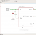
I tried to use https://www.mouser.com/ds/2/631/ACT4088_Datasheet-345917.pdf

Followed the example guide for step down 12V to 5V. Than, connected LM1117 on the 5V out to get 3.3 and now i have an issue. When i power up the circuit with 12V, everything works until i touch it with probe or some other wire.

The input is 12V 2.5A PSU

What could i do wrong?

p.s. I uploaded video in zip here, in case it can help to understand an issue..
 

Attachments

AlbertHall

Joined Jun 4, 2014
12,619
The 'EN' pin is clamped at 6V. Connected to 12V there could a be a very large current flowing into that pin. It only needs to be above 1.24V for the chip to work. For a quick check you could just disconnect it. It has an internal pull-up.
 

Thread Starter

nardev

Joined Feb 26, 2018
26
Ah, i noticed something very strange,

if i hold with my fingers the main 12V input, and touch some pads with wire in another hand, it doesn't happen :D

Must me some mess with potentials, grounding .. etc...

Any thoughts?
 

ebp

Joined Feb 8, 2018
2,332
The number one suspect is the long and sloppy wires to the external pot. The feedback resistors are in a high gain high bandwidth circuit and layout even on a PCB is important. Connecting one of the resistors with big long antennas and huge loop area is asking for trouble.

From the datasheet (and whoever expressed time in milli Siemens [mS]- you're fired!) it sounds like the device is going into hiccup mode as a result of severe overload - except it probably isn't overload it is probably just noise on the feedback input appearing like an overload.

Input and output power connections to the board should be twisted pairs: inductance matters.
 

Thread Starter

nardev

Joined Feb 26, 2018
26
The number one suspect is the long and sloppy wires to the external pot. The feedback resistors are in a high gain high bandwidth circuit and layout even on a PCB is important. Connecting one of the resistors with big long antennas and huge loop area is asking for trouble.

From the datasheet (and whoever expressed time in milli Siemens [mS]- you're fired!) it sounds like the device is going into hiccup mode as a result of severe overload - except it probably isn't overload it is probably just noise on the feedback input appearing like an overload.

Input and output power connections to the board should be twisted pairs: inductance matters.
:D can't be fired from a hobby project..

the original board converts input voltage to 3.3V immediately, i just wanted to see how good is the buck converter with some more devices on it.

Still don't know what to do to fix this.... :(
 

ebp

Joined Feb 8, 2018
2,332
Put a fixed resistor on the converter board instead of the the pot on long wires. It may not be that, but that is the place to start.

It isn't you that should be fired, it's whoever wrote the data sheet and used mS for time instead of ms.
 

Thread Starter

nardev

Joined Feb 26, 2018
26
Put a fixed resistor on the converter board instead of the the pot on long wires. It may not be that, but that is the place to start.

It isn't you that should be fired, it's whoever wrote the data sheet and used mS for time instead of ms.
I made the schematics but i don't see that mS there..

btw. with fixed resistors, on the other board, everything was fine.. but for 3.3V

I don't have those 0603 resistors and.. hate even to try soldering it..

However, i think that i missed some very important lessons for designing buck converters anyway.. especially PCB layout it propperly .. So i failed to realize how nasty it could be with so many wires and converter working is so messy environment :)
 
Top