Facebook
 Google
 GitHub
 Linkedin
hello,
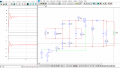
I'm trying to make an buck-boost, but i've a doubt about the inductor.
Can i use an inductor in common mode?
Or should the inductor have only one winding?
I'm trying to make an buck-boost, but i've a doubt about the inductor.
Can i use an inductor in common mode?
Or should the inductor have only one winding?