 Facebook
 Google
 GitHub
 Linkedin
Hi guys,
I am trying to control a 12V motor using arduino and BTS7960 in labVIEW. Here is the IC component: https://www.amazon.com/watersouprty-BTS7960-Double-Stepper-Driver/dp/B07XD4S7GF
I have LPWM and RPWM connected to pin 3 and 6 respectively.
I have L_EN and R_EN connected to pin 4 and 7 respectively.
Rest is just 5V and ground, straightforward.
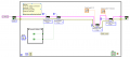
In labVIEW, I set L_EN and R_EN to be active. And created 2 control Knob for LPWM and RPWM.
I pretty much got the pump to work. The funny thing is, both LPWM and RPWM just makes the motor turn clockwise. So I am having trouble figuring out why it doesnt turn counter clockwise. Wonder if the board is just bad or if anyone have any suggestions/ideas that would be great.
I attached the labVIEW file snapshot below.
Thanks!
I am trying to control a 12V motor using arduino and BTS7960 in labVIEW. Here is the IC component: https://www.amazon.com/watersouprty-BTS7960-Double-Stepper-Driver/dp/B07XD4S7GF
I have LPWM and RPWM connected to pin 3 and 6 respectively.
I have L_EN and R_EN connected to pin 4 and 7 respectively.
Rest is just 5V and ground, straightforward.
In labVIEW, I set L_EN and R_EN to be active. And created 2 control Knob for LPWM and RPWM.
I pretty much got the pump to work. The funny thing is, both LPWM and RPWM just makes the motor turn clockwise. So I am having trouble figuring out why it doesnt turn counter clockwise. Wonder if the board is just bad or if anyone have any suggestions/ideas that would be great.
I attached the labVIEW file snapshot below.
Thanks!
Attachments
-
 31.5 KB Views: 24


