
 Facebook
 Google
 GitHub
 Linkedin
@BobTPH It is because you need to PWM one of the pins and keep the other low for one direction, but to switch direction, you PWM the other pin and keep the first pin low. The number of PWM channels on the MCU is limited to 8, but I need more. Hence why I plan on using this DPDT.
Brushed DC motor control IC killing MCU
- Thread starter Ephex
- Start date
Scroll to continue with content

I'm thinking you fried your MCU with the switching times you are using. It is also not clear how your controller (joysticks?) interface with the MCU.@BobTPH It is because you need to PWM one of the pins and keep the other low for one direction, but to switch direction, you PWM the other pin and keep the first pin low. The number of PWM channels on the MCU is limited to 8, but I need more. Hence why I plan on using this DPDT.
You mentioned using a Zener diode to protect the MCU from voltage spikes but this is more of a band-aid because it doesn't address the problem. From what I can tell, the bridge drivers you are using don't have extra protection which I why I recommended a flyback diode and snubber circuit.
If the spikes are from the FETs, this will clamp the voltage at the source of the problem. If you don't provide this kind of protection or upgrade your bridge drivers, you should stick to a super simple PWM scheme.
It is possible to detach PWM channels from GPIO pins, but I have had lots of issues with it. And "dead time" for safety may introduce a very annoying delay when letting off the throttle and starting to brake. This is why I want 4 GPIOs to always be assigned as PWMEither way, it requires 4 PWM signals. Can your MCU not assign the PWM to different outputs when changing direction? PICs can do that. If yours cannot it sounds like a poor design.
The controller has two triggers (basically springed triggers with magnets on them, and a hall-effect sensor that measures the angle) which give one byte of "throttle"/"brake" (0 to 255). These bytes are then sent to the car over ESP-NOW and used directly as PWM duty cycle (the PWM resolution is set to 8 bits), but duty cycles below 20% are set as 0%. This was only temporary code to try the thing out.I'm thinking you fried your MCU with the switching times you are using. It is also not clear how your controller (joysticks?) interface with the MCU.
You mentioned using a Zener diode to protect the MCU from voltage spikes but this is more of a band-aid because it doesn't address the problem. From what I can tell, the bridge drivers you are using don't have extra protection which I why I recommended a flyback diode and snubber circuit.
If the spikes are from the FETs, this will clamp the voltage at the source of the problem. If you don't provide this kind of protection or upgrade your bridge drivers, you should stick to a super simple PWM scheme.
4WD worked really well, and it didn't get fried (maybe because it was the first scenario, maybe because all motors were at low duty cycles). When I switched to RWD (and front wheels as brake), I had to apply higher throttle (in general) to accelerate which may have been a factor. During testing, me slamming the gas from 0% throttle to 100% throttle may have been within 100 ms (maybe even 50 ms?) which should be enough time for 25kHz PWM to have gone through a few periods to avoid unnecessarily high inrush currents. However, as I am writing this, I now remember that the code does not update PWM duty cycle (from the throttle value) at 25kHz, more like 100 Hz. This could lead to issues, no? If the trigger goes from 0% to 100% faster than the PWM duty cycle is updated, the PWM wave will first have 0% duty cycle, and then 100%, leading to a high inrush current? It may or may not have been the thing that ruined the MCU but definitely something to take into consideration for next time.
I am really confused about the snubber circuit. First I hear from @k1ng 1337 that one of these snubber circuits are needed for each bridge transistor (4 bridge transistors per H-bridge, right?) which would lead to 48 more components in my case. Then I hear from @BobTPH that "Just one snubber across each motor, preferably right at the motor terminals.". That would be better in terms of number of components, but I'm not sure how to use snubber circuits (including diodes) purely on the two motor ports when the motor will be driven in two directions.
Which one is it? 4 snubber circuits (one for each bridge transistor) for one motor, or 1 snubber circuit?
Which one is it? 4 snubber circuits (one for each bridge transistor) for one motor, or 1 snubber circuit?
25kHz is 40ms so you want the controller and MCU to update the new value(s) in less time than this in order to impress the full (or zero) voltage on the motor(s) as fast as possible because PWM is linked to a hardware timer. If MCU is doing other work (or sleeping) while it should be listening for the state of the H Bridges, it may enable PWM for the other direction before the motor(s) come to a halt. If there is current flowing and you suddenly give it no discharge path (or a poorly routed path), the voltage will rise until it finds a ground path (Power In = Power Out - Losses). I don't have enough experience to diagnose your circuit past this without taking a good look at your code and the entire circuit.The controller has two triggers (basically springed triggers with magnets on them, and a hall-effect sensor that measures the angle) which give one byte of "throttle"/"brake" (0 to 255). These bytes are then sent to the car over ESP-NOW and used directly as PWM duty cycle (the PWM resolution is set to 8 bits), but duty cycles below 20% are set as 0%. This was only temporary code to try the thing out.
4WD worked really well, and it didn't get fried (maybe because it was the first scenario, maybe because all motors were at low duty cycles). When I switched to RWD (and front wheels as brake), I had to apply higher throttle (in general) to accelerate which may have been a factor. During testing, me slamming the gas from 0% throttle to 100% throttle may have been within 100 ms (maybe even 50 ms?) which should be enough time for 25kHz PWM to have gone through a few periods to avoid unnecessarily high inrush currents. However, as I am writing this, I now remember that the code does not update PWM duty cycle (from the throttle value) at 25kHz, more like 100 Hz. This could lead to issues, no? If the trigger goes from 0% to 100% faster than the PWM duty cycle is updated, the PWM wave will first have 0% duty cycle, and then 100%, leading to a high inrush current? It may or may not have been the thing that ruined the MCU but definitely something to take into consideration for next time.
Take at a look a this table from Texas Instruments. All MOSFETs have a body diode but it may not conduct in a protective way. Figure 1 has flyback diodes which allows the current to recirculate according to the states of the transistors in Table 1. Since you have 4 motors, you should draw up a truth table similar to this. Ask yourself, is Table 1 showing ALL possible states of the H bridge? I'm still not sure if this is the problem but it seems to me you skipped this step.

The snubber circuits I showed are another way to clamp the voltage but aren't seen here.
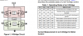
You cannot use a diode across a motor that is being reversed, but a snubber works equally well in both polarities, so it can be across the motor. In my opinion, it is better across the motor. That suppresses the transient at the source.Then I hear from @BobTPH that "Just one snubber across each motor, preferably right at the motor terminals.".
Can you provide insight into why only Csnub is needed and not the rest of the jumbo I posted?In fact, for best results the snubber should be connected directly across the motor terminals.
No, 25kHz has period 0.04 ms? Did you mean 40 μs?25kHz is 40ms so you want the controller and MCU to update the new value(s) in less time than this in order to impress the full (or zero) voltage on the motor(s) as fast as possible because PWM is linked to a hardware timer. If MCU is doing other work (or sleeping) while it should be listening for the state of the H Bridges, it may enable PWM for the other direction before the motor(s) come to a halt. If there is current flowing and you suddenly give it no discharge path (or a poorly routed path), the voltage will rise until it finds a ground path (Power In = Power Out - Losses). I don't have enough experience to diagnose your circuit past this without taking a good look at your code and the entire circuit.
For the rest of this part, do you mean that issues may occur if the direction is reversed when there is still current flowing? Or do you mean before the motor stops rotating ("[...] before the motor(s) come to a halt.")? Surely, it must be possible to apply positive torque (T > 0 as current has increased to positive i > 0), let the car gain some speed (angular velocity of motor > 0), and then apply a negative torque to brake (decelerate) while it is moving forward.
Of course, it won't be appropriate to switch the direction instantly when there is still a positive current flowing through the motor (if I understood your message). Having some dead time to let the current die off to 0A (through e.g. a snubber, or flyback diodes) before switching the direction of the applied voltage seems important.
Also, when the motor is turning, there will be back-emf present, which I suppose will have to be taken into consideration. It will in that case "help" the current decrease even faster.
For braking, maybe it's necessary not to allow switching of direction ("switch direction of applied voltage", forcing current the other way) when the motor is spinning? Instead, use "PWM motor braking" in the H-bridge until the speed reaches near zero, and then allow switching of the direction of the applied voltage?
The thing is that I do not have control over each bridge transistor (at least with the motor driver ICs I plan on using), only two logic gates. And why is it necessary to consider all 4 motors at the same time? They are driven by different H-bridges. Are you maybe purposing that something particular can occur if all motors are discharging through flyback diodes at the same time?Take at a look a this table from Texas Instruments. All MOSFETs have a body diode but it may not conduct in a protective way. Figure 1 has flyback diodes which allows the current to recirculate according to the states of the transistors in Table 1. Since you have 4 motors, you should draw up a truth table similar to this. Ask yourself, is Table 1 showing ALL possible states of the H bridge? I'm still not sure if this is the problem but it seems to me you skipped this step.
Of course, hence my question. An RCD snubber wouldn't work. That would leave me with either a Csnub (what was present on 1.2) or an RC snubber. Will the difference be substantial just by adding a resistor in series to the Csnub? If one RC snubber per motor is enough to help, that sounds nice, but @k1ng 1337 's more elaborate solution (having one snubber per bridge transistor) seems safer. Once again, adding 40+ components to an already cramped PCB is not something I prefer..You cannot use a diode across a motor that is being reversed, but a snubber works equally well in both polarities, so it can be across the motor. In my opinion, it is better across the motor. That suppresses the transient at the source.
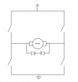
EDIT: Would it work to have two face-to-face zener diodes in parallel with the motor? Of course with high enough voltage not to conduct during max battery voltage, but maybe the same type of zener as the one that clamps VCC?

If there is current flowing when the motor is disconnected, won't the voltage rise until it reaches the zener clamp voltage and then let the current flow through the diodes in this example? On the contrary, I'm unsure about what happens when the spike dips below the "clamp" voltage, maybe the 100n capacitor will handle the rest?
Attachments
-
 24.4 KB Views: 0
Last edited:
I'll address your comments in bold with numbers to make it easier to follow. Before I do that, I want to point out my experience is limited so I have to be careful how I talk about this. Other users have offered competing suggestions so you should think about all of them while going back to relearn the theory (do the calculations!). I appreciate your frustration when one guy says something then another guy adds a twist to it so I'm offering what I think the problem is. The devil is in the details and you have a lot of details.No, 25kHz has period 0.04 ms? Did you mean 40 μs?
(1) For the rest of this part, do you mean that issues may occur if the direction is reversed when there is still current flowing? Or do you mean before the motor stops rotating ("[...] before the motor(s) come to a halt.")? Surely, it must be possible to apply positive torque (T > 0 as current has increased to positive i > 0), let the car gain some speed (angular velocity of motor > 0), and then apply a negative torque to brake (decelerate) while it is moving forward.
Of course, it won't be appropriate to switch the direction instantly when there is still a positive current flowing through the motor (if I understood your message). Having some dead time to let the current die off to 0A (through e.g. a snubber, or flyback diodes) before switching the direction of the applied voltage seems important.
Also, when the motor is turning, there will be back-emf present, which I suppose will have to be taken into consideration. It will in that case "help" the current decrease even faster.
For braking, maybe it's necessary not to allow switching of direction ("switch direction of applied voltage", forcing current the other way) when the motor is spinning? Instead, use "PWM motor braking" in the H-bridge until the speed reaches near zero, and then allow switching of the direction of the applied voltage?
(2) The thing is that I do not have control over each bridge transistor (at least with the motor driver ICs I plan on using), only two logic gates. And why is it necessary to consider all 4 motors at the same time? They are driven by different H-bridges. Are you maybe purposing that something particular can occur if all motors are discharging through flyback diodes at the same time?
1) A motor can be thought of as a flywheel like in a car or even a bike tire spinning. If you spin it with your hand, you can increase the RPM to the max force your arm can put out. As soon as your arm lets go per stroke, the flywheel acts as a generator where the stored energy is returned to the surroundings. In the case of a bike tire, the energy dissipates through friction. Now let's say you want to break while going down a hill, what happens if you slam on the brakes or try to pedal backwards (on an old school bike)? That energy has to go somewhere and will couple to every component in the bike it can. If you brake too quickly, everything locks up and you lose control, and, the gears and sprockets are stressed every time and they will soon deteriorate.
So, when a motor isn't powered by an external source while it is spinning, it will source current in the same direction until it comes to a halt. This is why we say a motor behaves like an inductive load. If you plan on using regenerative breaking or some other complex scheme to break or switch directions without accounting for this, the switching components will be stressed because the stored energy needs to dissipate. This is where dead time comes in. There has to be a certain amount of time to allow the switching devices to finish whatever they are doing before the code initiates a new command. This will be a intricate dance based on your PWM frequency, the components you selected and your ability to code. Specifically, dead time is about preventing shoot thought which can be seen in Table 1 above but the same concept applies when breaking or switching directions. You need to have a plan to do something with the current that flows. Since you have 4 motors possibility doing different things at once, you can imagine this getting messy quick.
2) This is somewhat moot to my points. Your entire circuit is on the same Vin so voltage spikes will always travel through a low current path generally to ground. I wouldn't expect your MCU to be destroyed unless you somehow managed to create a fault condition with the motors without providing an adequate discharge path. Again, the order at which you switch the bridges is critical because the difference between controlled deceleration and a short circuit is small as far as the bridges are concerned.
3) Forget what I said about snubber circuits for now. You seem to have to some holes in your understanding about motors so I think it would be a good idea for you to come up with a new schematic and possibly a flow chart if you can. Think about what I said about the possible states of each motor and how much time is needed to prevent a fault when and where it might occur.(3) Of course, hence my question. An RCD snubber wouldn't work. That would leave me with either a Csnub (what was present on 1.2) or an RC snubber. Will the difference be substantial just by adding a resistor in series to the Csnub? If one RC snubber per motor is enough to help, that sounds nice, but @k1ng 1337 's more elaborate solution (having one snubber per bridge transistor) seems safer. Once again, adding 40+ components to an already cramped PCB is not something I prefer..
EDIT: Would it work to have two face-to-face zener diodes in parallel with the motor? Of course with high enough voltage not to conduct during max battery voltage, but maybe the same type of zener as the one that clamps VCC?
If there is current flowing when the motor is disconnected, won't the voltage rise until it reaches the zener clamp voltage and then let the current flow through the diodes in this example? On the contrary, I'm unsure about what happens when the spike dips below the "clamp" voltage, maybe the 100n capacitor will handle the rest?
Also, you mentioned two different versions of your project so it's hard to know what is really going on. You'll get better responses if you make your questions easy to read and follow. As you found out, some people wont help until you step up your presentation style which is a harsh lesson but is still good for you in the long run.
@k1ng 1337 First of all, I really appreciate you taking the time to help me through all this.
On the other hand, it feels like this thread has been a lot of "running in circles" with evenly spread misunderstandings. I tried to make it clear early on that v1.2 was the first version, and the one that broke as well as that v2.0 is WIP and has not yet been ordered. Despite this, I was asked how the code looked for using the analog switch, as if I had assembled v2.0. This may have been because I in the first post wrote
Maybe it's time to round things off with somewhat of a summary. But one last thing; in post #31 I wrote this:
Please let me know if I have understood you incorrectly!
I personally feel comfortable with the "RL+backemf" model of a brushed DC motor, it is just the physical implementation as well as PWM switching issues that is bugging me. Also, the transitions between different operating modes based on PWM and the inputs of the user are clearly something I have to take a closer look into. The different motors affecting each other is also something I did not think about.
I have also learned that the most clear issue with v1.2 was the fact that both Vm and Vdd were connected to battery voltage, instead of Vm->VCC and Vdd->3.3V. This combined with inductive voltage spikes from switching might have caused the MCU to die.
Here's what I have added to v2.0 during the course of this thread:
I will spend some more time trying to see if there are other 2+ channel motor driver ICs with clearly depicted flyback diodes and/or built-in snubber circuits. Also, the code needs to apply reasonable PWM waves to the logic gates depending on the operating modes of the motors.
EDIT: I think I found what looks to be flyback diodes in the datasheet for the A3909GLNTR-T driver that I planned on using for v2.0:
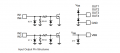
The one up to the right seems to say that there is one diode between GND and each output as well as between each output and supply voltage. Do you agree?
On the other hand, it feels like this thread has been a lot of "running in circles" with evenly spread misunderstandings. I tried to make it clear early on that v1.2 was the first version, and the one that broke as well as that v2.0 is WIP and has not yet been ordered. Despite this, I was asked how the code looked for using the analog switch, as if I had assembled v2.0. This may have been because I in the first post wrote
which could have been interpreted as two different designs, which it was not. Either way, I guess it was me not being clear enough."Two separate times on two different boards (v1.2 of the PCB) with different components"
Maybe it's time to round things off with somewhat of a summary. But one last thing; in post #31 I wrote this:
This was in response to your statement:For the rest of this part, do you mean that issues may occur if the direction is reversed when there is still current flowing? Or do you mean before the motor stops rotating ("[...] before the motor(s) come to a halt.")? Surely, it must be possible to apply positive torque (T > 0 as current has increased to positive i > 0), let the car gain some speed (angular velocity of motor > 0), and then apply a negative torque to brake (decelerate) while it is moving forward.
By "come to a halt", do you mean the speed of the motor coming to zero? If this is what you meant, is it really necessary for the back-emf to go to 0V to switch direction? As long as you consider it when "selecting" the voltage to apply, it shouldn't be a problem? Of course, if the back-emf builds up to 8V and you switch the sign of the armature voltage to -8V, you pretty much push 16V through an RL circuit.[...] it may enable PWM for the other direction before the motor(s) come to a halt
Please let me know if I have understood you incorrectly!
I personally feel comfortable with the "RL+backemf" model of a brushed DC motor, it is just the physical implementation as well as PWM switching issues that is bugging me. Also, the transitions between different operating modes based on PWM and the inputs of the user are clearly something I have to take a closer look into. The different motors affecting each other is also something I did not think about.
I have also learned that the most clear issue with v1.2 was the fact that both Vm and Vdd were connected to battery voltage, instead of Vm->VCC and Vdd->3.3V. This combined with inductive voltage spikes from switching might have caused the MCU to die.
Here's what I have added to v2.0 during the course of this thread:
- A zener diode to clamp VCC voltage
- A zener diode to clamp 3.3V
- Optocouplers for every logic/PWM pin
I will spend some more time trying to see if there are other 2+ channel motor driver ICs with clearly depicted flyback diodes and/or built-in snubber circuits. Also, the code needs to apply reasonable PWM waves to the logic gates depending on the operating modes of the motors.
EDIT: I think I found what looks to be flyback diodes in the datasheet for the A3909GLNTR-T driver that I planned on using for v2.0:
The one up to the right seems to say that there is one diode between GND and each output as well as between each output and supply voltage. Do you agree?
Last edited:

Yes, Rule #1 for motor control reliability. Power bus isolation.@k1ng 1337 First of all, I really appreciate you taking the time to help me through all this.
...
I have also learned that the most clear issue with v1.2 was the fact that both Vm and Vdd were connected to battery voltage, instead of Vm->VCC and Vdd->3.3V. This combined with inductive voltage spikes from switching might have caused the MCU to die.
Here's what I have added to v2.0 during the course of this thread:
...
- A zener diode to clamp VCC voltage
- A zener diode to clamp 3.3V
- Optocouplers for every logic/PWM pin
400Hz 3-phase 100W inverter.
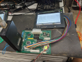
PWM to three DC brushed motors using the first version of the board, controller DC separated source from the ICD-4.
Same board driving Quadrature Phase 400Hz Motor.
Attachments
-
87.6 KB Views: 2
-
331 KB Views: 2
Last edited:
Sounds like you may have found the problem but I think you need to spend more time thinking about what a PWM signal is and how it interacts with the motor(s). I usually design all my projects from scratch whereas you are building on other people's technology (the bridge IC for example). This isn't a bad thing but it often takes away the practical A-B-C thought process from the builder. Naturally, it will be difficult to understand the nuts and bolts of a system if you haven't been exposed to them.@k1ng 1337 First of all, I really appreciate you taking the time to help me through all this.
On the other hand, it feels like this thread has been a lot of "running in circles" with evenly spread misunderstandings. I tried to make it clear early on that v1.2 was the first version, and the one that broke as well as that v2.0 is WIP and has not yet been ordered. Despite this, I was asked how the code looked for using the analog switch, as if I had assembled v2.0. This may have been because I in the first post wrote
which could have been interpreted as two different designs, which it was not. Either way, I guess it was me not being clear enough.
Maybe it's time to round things off with somewhat of a summary. But one last thing; in post #31 I wrote this:
This was in response to your statement:
By "come to a halt", do you mean the speed of the motor coming to zero? If this is what you meant, is it really necessary for the back-emf to go to 0V to switch direction? As long as you consider it when "selecting" the voltage to apply, it shouldn't be a problem? Of course, if the back-emf builds up to 8V and you switch the sign of the armature voltage to -8V, you pretty much push 16V through an RL circuit.
Please let me know if I have understood you incorrectly!
I personally feel comfortable with the "RL+backemf" model of a brushed DC motor, it is just the physical implementation as well as PWM switching issues that is bugging me. Also, the transitions between different operating modes based on PWM and the inputs of the user are clearly something I have to take a closer look into. The different motors affecting each other is also something I did not think about.
I have also learned that the most clear issue with v1.2 was the fact that both Vm and Vdd were connected to battery voltage, instead of Vm->VCC and Vdd->3.3V. This combined with inductive voltage spikes from switching might have caused the MCU to die.
Here's what I have added to v2.0 during the course of this thread:
- A zener diode to clamp VCC voltage
- A zener diode to clamp 3.3V
- Optocouplers for every logic/PWM pin
I will spend some more time trying to see if there are other 2+ channel motor driver ICs with clearly depicted flyback diodes and/or built-in snubber circuits. Also, the code needs to apply reasonable PWM waves to the logic gates depending on the operating modes of the motors.
EDIT: I think I found what looks to be flyback diodes in the datasheet for the A3909GLNTR-T driver that I planned on using for v2.0:
View attachment 310594
The one up to the right seems to say that there is one diode between GND and each output as well as between each output and supply voltage. Do you agree?
I've had a single H bridge and motor sitting on the breadboard for the past 3 weeks that I'm still troubleshooting. Even with my homemade and extremely simple PWM schemes, some very sneaky faults have occurred which blew up a few transistors. My project is a bit different than yours but voltage spikes are definitely a problem for my setup.
You are headed in the right direction with finding ways to isolate the power bus from the data bus. If I were you, I'd rebuild the project on the breadboard piece by piece and test it, especially the bridge sections.
If you haven't already, try out LTspice circuit simulator. It is free and extremely useful for understanding a complex circuit. Motors are tough to model but you can get a good approximation which will definitely fill in your understanding of them.
Actually, 2-3 years ago I designed a brushed DC PWM controller PCB. It was an H-bridge from scratch and I learned a lot about MOSFETs at the time. Sadly, I have never had an oscilloscope so it was quite difficult to see the switching happening beneath the surface. It had some issues with getting started but worked decently well. No MCUs were fried, but the PWM duty cycles did not change as violently as with this car...Sounds like you may have found the problem but I think you need to spend more time thinking about what a PWM signal is and how it interacts with the motor(s). I usually design all my projects from scratch whereas you are building on other people's technology (the bridge IC for example). This isn't a bad thing but it often takes away the practical A-B-C thought process from the builder. Naturally, it will be difficult to understand the nuts and bolts of a system if you haven't been exposed to them.
I've had a single H bridge and motor sitting on the breadboard for the past 3 weeks that I'm still troubleshooting. Even with my homemade and extremely simple PWM schemes, some very sneaky faults have occurred which blew up a few transistors. My project is a bit different than yours but voltage spikes are definitely a problem for my setup.
You are headed in the right direction with finding ways to isolate the power bus from the data bus. If I were you, I'd rebuild the project on the breadboard piece by piece and test it, especially the bridge sections.
If you haven't already, try out LTspice circuit simulator. It is free and extremely useful for understanding a complex circuit. Motors are tough to model but you can get a good approximation which will definitely fill in your understanding of them.
I'll get back to you guys in a week when v2.0 has been ordered, received, assembled and tested!
You can pick up a pocket scope for 40 bucks which is good to around 200kHz. Not so great for spotting transients but at least you can verify what's happening with the 25kHz PWM signals in real time. I have a "DSO150" which has served me well.Actually, 2-3 years ago I designed a brushed DC PWM controller PCB. It was an H-bridge from scratch and I learned a lot about MOSFETs at the time. Sadly, I have never had an oscilloscope so it was quite difficult to see the switching happening beneath the surface. It had some issues with getting started but worked decently well. No MCUs were fried, but the PWM duty cycles did not change as violently as with this car...
I'll get back to you guys in a week when v2.0 has been ordered, received, assembled and tested!
Keep us updated and sorry if I created more confusion than answers. I decided to give it a shot and it looks like you will get to the bottom of this.





