Facebook
 Google
 GitHub
 Linkedin
Hi all
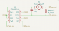
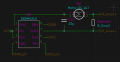
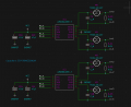
I have a PCB I made for an RC car which somehow kills the MCU. Two separate times on two different boards (v1.2 of the PCB) with different components, it worked fine for 30-40 minutes before one motor gave up, and the MCU shortly after (MCU got hot, 10 Ohm between 3.3V and GND on the board). v1.2 of the PCB features 4 DC motor controllers and an ESP32-S3-WROOM-1-N8. REV_pin and FWD_pin are connected directly to GPIO pins on the ESP32. The motor ICs are connected as such:
(Rsense2 is a mere 0.01 Ohm for current measurement)
I have learned from a Reddit post that Vm and Vdd are not supposed to both be connected to the battery (2S LiPo, ~8V) despite the data sheet saying "Power Supply Voltage" for both VDD and VM (my mistake). This could very easily have been the thing that caused the MCUs to die after a while, but I'm not sure how it could have happened. Did the logic pins of the motor IC somehow push current the other way into the ESP, destroying it? Did a voltage spike (when a motor got turned off) kill the ESP through BAT+ -> LDO -> ESP32 (there were plenty of capacitors around the LDO though)?
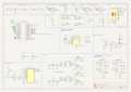
I have designed a new version (v2.0) with most components getting switched out. There are now two dual-channel DC controllers as well as DPDT analog switches to only require one PWM channel for each motor (a total of 8 channels for the ESP32-S3 are available, but I need more).
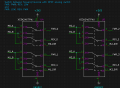
FWR_x and REV_x for each motor are connected to GPIO pins on the ESP32, enabling one to be PWM and the other a digital out. The analog switch enables me to change how they are connected to the motor ICs using one bit (Mx_DIR). This is not an attempt at fixing the issue, only to not need more PWM channels. This brings me to my first question:
1. Do I need something between the GPIO pins and the motor IC logic input? A resistor? Opto-coupler?
I have also left capacitors in parallel with each motor (C_M):
2. Are the capacitors C_M needed? What value in that case? Will they affect the system in a good or bad way? It feels a bit off.
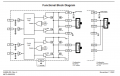
The new motor drivers felt more straightforward compared to the old ICs, but they lack a bit in terms of documentation. There are no flyback-diodes in the schematic for the H-bridge and they don't mention it anywhere. They have plenty of "XXXXX protection" but I don't feel certain.
3. Are separate flyback diodes needed for this new IC?
4. How does one handle the voltage transients and back-emf from the motor?
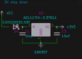
Here is the LDO that converts battery power to 3.3V:
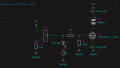
Also, my attempt at switching the battery with a tiny switch (SW4):
Is anything weird/questionable with my design?
Truly grateful for all the feedback I can get!
// Ephex
I have a PCB I made for an RC car which somehow kills the MCU. Two separate times on two different boards (v1.2 of the PCB) with different components, it worked fine for 30-40 minutes before one motor gave up, and the MCU shortly after (MCU got hot, 10 Ohm between 3.3V and GND on the board). v1.2 of the PCB features 4 DC motor controllers and an ESP32-S3-WROOM-1-N8. REV_pin and FWD_pin are connected directly to GPIO pins on the ESP32. The motor ICs are connected as such:
(Rsense2 is a mere 0.01 Ohm for current measurement)
I have learned from a Reddit post that Vm and Vdd are not supposed to both be connected to the battery (2S LiPo, ~8V) despite the data sheet saying "Power Supply Voltage" for both VDD and VM (my mistake). This could very easily have been the thing that caused the MCUs to die after a while, but I'm not sure how it could have happened. Did the logic pins of the motor IC somehow push current the other way into the ESP, destroying it? Did a voltage spike (when a motor got turned off) kill the ESP through BAT+ -> LDO -> ESP32 (there were plenty of capacitors around the LDO though)?
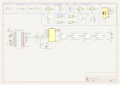
I have designed a new version (v2.0) with most components getting switched out. There are now two dual-channel DC controllers as well as DPDT analog switches to only require one PWM channel for each motor (a total of 8 channels for the ESP32-S3 are available, but I need more).
FWR_x and REV_x for each motor are connected to GPIO pins on the ESP32, enabling one to be PWM and the other a digital out. The analog switch enables me to change how they are connected to the motor ICs using one bit (Mx_DIR). This is not an attempt at fixing the issue, only to not need more PWM channels. This brings me to my first question:
1. Do I need something between the GPIO pins and the motor IC logic input? A resistor? Opto-coupler?
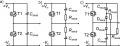
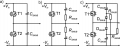
I have also left capacitors in parallel with each motor (C_M):
2. Are the capacitors C_M needed? What value in that case? Will they affect the system in a good or bad way? It feels a bit off.
The new motor drivers felt more straightforward compared to the old ICs, but they lack a bit in terms of documentation. There are no flyback-diodes in the schematic for the H-bridge and they don't mention it anywhere. They have plenty of "XXXXX protection" but I don't feel certain.
3. Are separate flyback diodes needed for this new IC?
4. How does one handle the voltage transients and back-emf from the motor?
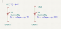
Here is the LDO that converts battery power to 3.3V:
Also, my attempt at switching the battery with a tiny switch (SW4):
Is anything weird/questionable with my design?
Truly grateful for all the feedback I can get!
// Ephex

 . The grid might get removed though.