 Facebook
 Google
 GitHub
 Linkedin

Specifications:
Input voltage:10-24VDC, recommended 18V wall power supply(Power Jack)
Output voltage: 3.3V/5V/Adjustable 1.8-12V
Output current: 650mA
Pin Headers for input and output
Central positive DC 2.1 power jack for input
Size: 2.64” x 1.69”
Project Description
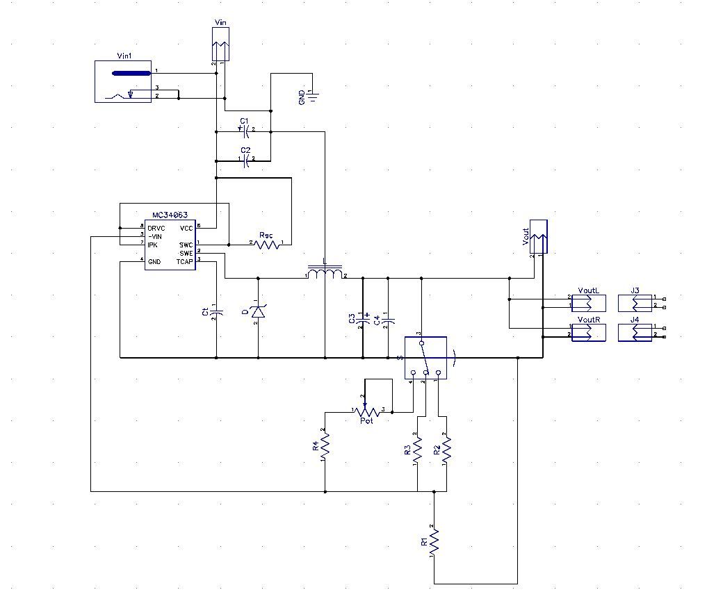
Switching mode power supply is much more efficient and have wider range of input voltages than linear regulator.
Input voltage of this Breadboard Power Supply is 10-24V DC (Recommended 18V wall power supply) (Power Jack with positive center pin)
Maximum current at output of this power supply is 650mA and no heat sinks are needed.
Module also have adjustable voltage output in ranges between 1.8-12 Volts but in that case input voltage should be in range from 18 to 24 Volts, maximum output current in adjustable mode is 500mA.
If 10 Volts are applied on input – output voltage can be adjusted in range from 1.8V to 6V, maximum upper voltage level in adjustable mode is increased as input voltage increases.
3.3V 5V and adjustable modes are selected with three position slide switch, in adjustable mode voltage is adjusted with potentiometer.
Distance between closer pins on headers on opposite sides used for Breadboard inserting is 1.7 Inches (43.18 mm) and they fit on breadboard which is built on that standard.
Module can’t be inserted on some Breadboards so header on one side (Vout R or Vout L) should not be soldered if this module is used on that Breadboard with different dimensions between power rails.
PCB dimensions are 67 × 43mm (2.64 × 1.69 Inches)
This module will ideally work with 18V DC power supply adapter.
More info about this project can be found in the Project files
") (components, schematic, some basics about circuit and similar stuff).
(components, schematic, some basics about circuit and similar stuff).If you want to source quality components fast this project can be bought as kit on Jameco electronics site (Professional made PCB is included):
Breadboard Power Supply Module 3.3V or 5V output
Attachments
-
485.4 KB Views: 129


