I don't know if things have changed in the 30 years since I used to travel there to support a security system at Montreal Bordeaux Prison but shipping anything (including me) was always a huge hassle. It got to the point where I would ship my tools and test equipment ahead of me and tell the immigration folks I was there for a vacation. But then I would have to chase on down to the customs office to retrieve my equipment. No idea what fees my company had to pay but I know it was not cheap.
I'll post pics of my power supply after I find out if it can be dealt with by the seller. I'm not going to start taking it apart just yet, until I know if I'm stuck with it or not.
bt if you look above I linked to a thread somewhere, and someone took a bunch of pictures inside of one of these.
just realied I missed a bunch of posts.
Thanks for the schematic, I'm not sure where you found it but when I looked for "hy3005f schematic" and similar terms, I didn't turn up anything.
I should hear back from the seller today as to what can be done. They were checking to see if they could refund me the entire $356 even though they only received $231 from me.
I don't really want to return it though because it seems like a decent supply so far aside from this one (fairly significant) problem
The long white board is the board that has the pots mounted to it.
The large green one near the bottom of the image is where the displays are mounted, and the small board near the transformer is the 5V constant board.
Thinking on it now, there's a chance it may be those big transistors on the back causing the problem.
I remember reading something someone wrote about a problem with their power supply and they had to remove those transistors to fix a grounding/short problem.
What would be the correct way to test those transistors in-circuit before attempting to remove them (they didn't make it easy)?
Tested a couple of other things, here's where I'm at now.
On the slave channel, I measured the voltage going to the 3 transistors between the base(s) and collector(s), with the pots adjusted all the way to "0V" there was 14V at the transistors. as I turned the pots to adjust the voltage higher, the voltage at the transistors would slowly drop until the relay kicked in where it would then jump up to it's next "step" so to speak.
This was normal operation of the slave channel.
On the master channel the voltage at the transistors remained at 14V no matter how I adjusted the voltage output adjustment pot.
If I feed the output of the 5V constant channel to the output plugs on the master channel, the relays click, and the voltage meter on the power supply shows 5V.
so I'm thinking that somewhere on that long white control board is the problem.
Can anyone identify the problem? look closely, it's a tricky one.
Thanks to the schematic posted above though, I can see that I need to go buy a 1k pot. but while I'm in here, I could replace the pots for something slightly more fine
I'll look around and see if I can find a schematic....that could take a while though.
of note is the fact that when I adjust the voltage knob, there is no clicking of relay's as there is with the slave channel.
However, the slave channel relays click at about 4V, and since I don't even get any output on the master channel I can assume that something is not getting to the "supply board" for the master channel.
where this becomes a problem is that I have to practically take apart the entire unit just to get to the smaller boards on the front panel.
I don't have an 11th pic of my own, but I did reseat everything and check that everything was plugged in.
I had to order replacement pots from digikey so they won't be here until tomorrow, then I can get to replacing the pot and putting it all back together.
I wish I could find a pot like this in a 3 turn though.
I'm sure you've found what caused the problem.If the coarse voltage pot is removed,it will result in zero output.
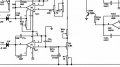
By the way,when looking at the schematic today and trying to understand how it works,I time and time again concluded that it can't!
How is that possible?Simply because there's an error in the schematic!
It concerns the voltage adjustment and the connection between -N1 and V26A emitter.This connection shouldn't be there-it only confuses you and instead both should be connected to ground.
To my horror I discovered that this error is present in HY3002,HY3005,HY3010.Only HY3020 is correct!
A redrawn schematic below.
Comments are certainly welcome!
I don't think that drawing is for this model exactly, but for the single channel model.
The one I have is a HY3005F-3 which is different from the HY3005
Also, the pots are different than what is labeled on the board. My broken pot (W5) is a 1K on the physical board, but the diagram shows it as a 6.8K, but 6.8K pots are what's installed for the current adjustments.
Hey brother if you have technical knowledge than you must go for troubleshooting otherwise it is dangerous for you and this product. Secondly for my opinion check the input first that comes in the board and if it is OK than check all the diodes and transistors by multimeter. If relay is not clicking than check voltage across its poles that must be 4v and still its not working than relays are bad.
Hey brother if you have technical knowledge than you must go for troubleshooting otherwise it is dangerous for you and this product. Secondly for my opinion check the input first that comes in the board and if it is OK than check all the diodes and transistors by multimeter. If relay is not clicking than check voltage across its poles that must be 4v and still its not working than relays are bad.
 Facebook
 Google
 GitHub
 Linkedin


")