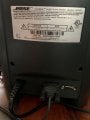
Bose CineMate DB9 connector pinout?

If you have a service manual and/or schematic, I'd very much appreciate you sharing it with me. I still haven't been able to figure out the circuit and have had no luck getting it working. I've determined that the power transformer and main power supply is working along with a voltage regulator IC. But the unit is not sending any power to the status LED on the input box, neither red for off or green for on, and the unit is unresponsive to the remote control. I assume what failed is in the power control circuit and I could probably figure it out with some documentation. I have it all apart in a corner with all the loose parts in a shoe box on top of it. It really like to get it working again because it had such a good sound. But if I don't figure it out soon, it will be making its way to the recycling center. Thanks in advance for your help!
Sorry it took a bit to find it, I’m recovering from oral surgery.

Besides the Service Manual, I also have several Service Bulletins in regards to special issues.
I don’t know how many files I can attach but I’ll try several messages if I can.
They might be out of order but I’m sure you can sort them out. It should be 10 files.
 

Attachments

VPTech65

Joined Jun 25, 2023
6
Thanks for sending the documentation and sorry for taking so long to acknowledge. I was really busy for a few months and finally just got back into it yesterday and tonight after work. Unfortunately this isn't the model I have. This says it's for a "series II" and I believe I have the first old original Cinnemate. On mine, there is no separate power supply board, and the output from the transformer goes directly into the main board. And mine has no volume control on the back side, just the power in and the 2 9-pin connectors for the speakers and IR sensor board. If you (or anyone) would happen to have any documentation on the older model I have, once again, I'd really appreciate it. The power supply sections are working as far as I can tell. I'm measuring 5V and 3.3V at various points but it's not sending any voltage to the indicator LED. Supposed to be red for off and green when on but no light at all and no response from the remote. Thanks again
 
Thanks for sending the documentation and sorry for taking so long to acknowledge. I was really busy for a few months and finally just got back into it yesterday and tonight after work. Unfortunately this isn't the model I have. This says it's for a "series II" and I believe I have the first old original Cinnemate. On mine, there is no separate power supply board, and the output from the transformer goes directly into the main board. And mine has no volume control on the back side, just the power in and the 2 9-pin connectors for the speakers and IR sensor board. If you (or anyone) would happen to have any documentation on the older model I have, once again, I'd really appreciate it. The power supply sections are working as far as I can tell. I'm measuring 5V and 3.3V at various points but it's not sending any voltage to the indicator LED. Supposed to be red for off and green when on but no light at all and no response from the remote. Thanks again
I believe I have the same one you described. IMG_1692.jpeg
The pinout diagram I drew is correct for the IR Remote unit but you needed the speaker side pinout?
I made some measurements of those pins with my Oscilloscope while inputting different frequencies in each channel and it’s rather confusing what the output is.
The internal DSP reduces certain frequencies and passes others that are higher and lower.
I though from what I’ve read that each side L & R has 4 pins per side, with 2 going to a “high” or Tweeter and 2 going to a “mid” or woofer driver respectively.
The output board has 4 thicker traces and 4 thinner traces going to the 9-pin output jack, with one pin unused.
This led me to believe the thicker traces went to the mid woofer since lower frequencies naturally require more power to produce.
However, after measuring the signals I input, hoping to confirm this and identify the L and R channels, I am left more confused than before.
I think the ground is somewhat shared (they call it something like quasi-separate ground I think) and crossing signals are managed intentionally by the board for presumably better sound results.
But i don’t know for sure yet.
I will check my notes on what I measured incase they offer further insight to anything.
Good luck.
 

VPTech65

Joined Jun 25, 2023
6
I got the remote board pretty much figured out and the problem is not there. It's not getting any LED power into it from the main board. So what I'm trying to figure out is what could have died on the main board to cause the LED to not light up at all or respond to the remote. It should be sending an on or off state indication but sending neither so the power on/off section wherever it's located isn't working. Thanks again for all your help!
 
I got the remote board pretty much figured out and the problem is not there. It's not getting any LED power into it from the main board. So what I'm trying to figure out is what could have died on the main board to cause the LED to not light up at all or respond to the remote. It should be sending an on or off state indication but sending neither so the power on/off section wherever it's located isn't working. Thanks again for all your help!
I’m sure you probably checked this already but just in case, did you check continuity through the remote units cable?
Also, from the board it plugs into through connectors to the ribbon cables that come out of it.
If the on/off signal isn’t getting through it could produce similar symptoms.
 
Top