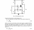
According to Ohm`s law, the current through R3 is i=(vin-Avin)/R3.
Therefore, the coresponding conductance is i/vin=(1-A)/R3 and the corresponding resistance is vin/i=R3/(1-A) which is much larger than R3 because A<1 (but very close to unity).
This calculation assumes that the capacitor C is rather large (capacitive impedance negligible).
This "bootstrap" method is a kind of positive feedback which increass the input impedance drastically.
According to Ohm`s law, the current through R3 is i=(vin-Avin)/R3.
Therefore, the coresponding input conductance is i/vin=(1-A)/R3 and the corresponding resistance is vin/i=R3/(1-A) which is much larger than R3 because A<1 (but very close to unity).
This calculation assumes that the capacitor C is rather large (capacitive impedance negligible).
This "bootstrap" method is a kind of positive feedback which increass the input impedance drastically.
First, notice that if the R3 resistor was connected between Vin and GND any change in Vin will cause corresponding change R3 resistor current i = vin/R3 hence rin = R3.
But in this circuit R3 resistor is connected between Vin and emitter. As you shoud know the AC voltage at the emitter follows the input voltage vin ≈ v_emitter. This means that the voltage across R3 is constant, hence for the AC signals, the R3 looks like a constant current source (a bigger resistor).
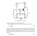
Examine this
When we have an ideal voltage amplifier with the voltage gain equal to A.
First, notice that if the R3 resistor was connected between Vin and GND any change in Vin will cause corresponding change R3 resistor current i = vin/R3 hence rin = R3.
But in this circuit R3 resistor is connected between Vin and emitter. As you shoud know the AC voltage at the emitter follows the input voltage vin ≈ v_emitter. This means that the voltage across R3 is constant, hence for the AC signals, the R3 looks like a constant current source (a bigger resistor).
Hello, I understand that this is quite an old post, but can someone please tell me what document/book the screenshot in the original post came from? I would like to find a copy of it as the small snippet is written in a manner that I can easily digest and that makes me think the rest of the document will be as well. Any direction as to where to find it would be appreciated.
 Facebook
 Google
 GitHub
 Linkedin
 278.6 KB Views: 51