"Does not work" is not very descriptive. That's like saying "my car doesn't run."
How does it not work?
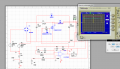
There appears to be a missing connection between R4 and the gate of Q1.
"Does not work" is not very descriptive. That's like saying "my car doesn't run."
How does it not work?
There appears to be a missing connection between R4 and the gate of Q1.
As Mike stated, the op amp needs plus and minus supplies to operate in your circuit.
It cannot operate with a single supply with the + input grounded.
If you look at the data sheet for that op amp (gasp) you will see that the input common-mode range can go no lower than about 3V above the negative voltage rail.
Maybe the op amp is just drawn upside down and Vcc is 15 volts and ground is ground, but in either case the - input will always be higher than the + input (ground) so the output will always be ground.
What is U1 and the amplitude and frequency of the sawtooth feeding it?
Maybe the op amp is just drawn upside down and Vcc is 15 volts and ground is ground, but in either case the - input will always be higher than the + input (ground) so the output will always be ground.
......................
As Mike stated, the op amp needs plus and minus supplies to operate in your circuit.
It cannot operate with a single supply with the + input grounded.
If you look at the data sheet for that op amp (gasp) you will see that the input common-mode range can go no lower than about 3V above the negative voltage rail.
Maybe the op amp is just drawn upside down and Vcc is 15 volts and ground is ground, but in either case the - input will always be higher than the + input (ground) so the output will always be ground.
What is U1 and the amplitude and frequency of the sawtooth feeding it?
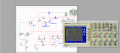
You don't show the input polarity of the comparator, U1.
That would be a problem if it's incorrect.
Measure the voltage waveform at:
the output of the op amp,
the output of the comparator,
the sawtooth waveform,
the MOSFET drain.
Post those with the vertical and horizontal scale indication.
The voltage rating of D2 is too low. It needs to be over 400V.
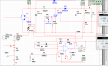
With a 10 ohm resistor in series with the gate, the diode likely will have little effect on the turn-on time.
The source voltage of Q1 should go to ground when it is ON and it's not, so that's a problem.
You need to determine why it's not going to ground.
Check the current through L1.
thanks so much, the circuit in the lab it works , but I do not know why the simulation is not , the source connected to the common when the gate is on in the lab but in simulation is not
thanks so much, the circuit in the lab it works , but I do not know why the simulation is not , the source connected to the common when the gate is on in the lab but in simulation is not
 Facebook
 Google
 GitHub
 Linkedin
 78.7 KB Views: 12