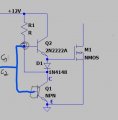
R1, Q2, D1 = parts
Q1a+b = IC
Q2 pulls up when Q1 is open.
Q1 (inside the TL494) pulls down. Q1=two transistors.
The TL494 was never designed to drive MOSFETs. I have used the TL494 many times like this picture.
R1, Q2, D1 = parts
Q1a+b = IC
Q2 pulls up when Q1 is open.
Q1 (inside the TL494) pulls down. Q1=two transistors.
The TL494 was never designed to drive MOSFETs. I have used the TL494 many times like this picture. View attachment 206581
I'm sorry but I asked my teacher and he said tl494 can drive the fet directly. I don't think the problem is there, because then my circuit can't work. However, my circuit gave an output voltage of approximately 60 volts but then it was reduced and there was no stability at 60 volts.
I'm sorry but I asked my teacher and he said tl494 can drive the fet directly. I don't think the problem is there, because then my circuit can't work. However, my circuit gave an output voltage of approximately 60 volts but then it was reduced and there was no stability at 60 volts.
Well if you use the two output collectors you may be able to pull it off, but whenever you drive a MOSFET with a somewhat large value resistor dont expect to get fast switching.
Using two outputs in parallel the average drive current to shut off the mosfet would be about 200ma max with the right choice of pullup resistors, which isnt that good really.
Note that the TL598 has total pole outputs while the TL494 has open collector outputs, and all the reference designs for the TL494 use bipolars on the output not mosfets, while some of the TL598 reference designs use MOSFETs.
But what current are you expecting to draw on the output of this?
 Facebook
 Google
 GitHub
 Linkedin
 11.9 KB Views: 24