boost converter with TL494

Thread Starter

toandang

Joined May 7, 2020
12
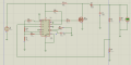
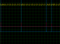
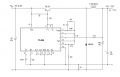
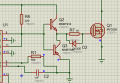
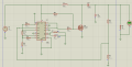
Hello everybody, now I am designing dc dc boost converter circuit using TL494, from 12V up 60V. But I am having a few issues that are giving me a headache. I have designed the circuit as attached, but it does not work as I expected. Someone please tell me where I went wrong.
thanks all
 

Attachments

Alec_t

Joined Sep 17, 2013
14,329
As presently wired Q1 may not turn off completely because its gate is not pulled down to ground.
R6 should connect directly to the U1 collectors: not to the Q1 gate.
 

MisterBill2

Joined Jan 23, 2018
18,568
As presently wired Q1 may not turn off completely because its gate is not pulled down to ground.
R6 should connect directly to the U1 collectors: not to the Q1 gate.
In fact, I see no reason for R6 to be there at all. What is the reason that R6 was included? It is far to low a resistance to be connected to the FET gate, it may have been connected to someplace else in the circuit you used as a reference.
 

Thread Starter

toandang

Joined May 7, 2020
12
I corrected the circuit according to the board's wishes, connecting R6 to pin C, but the problem is still unresolved, the output voltage increases to approximately 60V and then drops without any stability. I think there is another problem???
 

Attachments

ronsimpson

Joined Oct 7, 2019
3,043
It looks like the MOSFET is turned on one out of ten cycles. And the on time is very short. It looks like the error amp thinks you are at or near regulation.
I also see there are no capacitors on the error amplifier.
I think the error amp may be oscillating.
What is your load?
What is the inductor? (picture or part number)
 

ronsimpson

Joined Oct 7, 2019
3,043
I don't think there's a difference here
Error amp 0.1uF & 47K // 1M
Your error amp is running with low gain and that is probably ok for now.

The "Comp" pin is low for high duty cycle and high for small on time. I think the Comp pin is running very high. It thinks you have voltage.
 

Thread Starter

toandang

Joined May 7, 2020
12
It looks like the MOSFET is turned on one out of ten cycles. And the on time is very short. It looks like the error amp thinks you are at or near regulation.
I also see there are no capacitors on the error amplifier.
I think the error amp may be oscillating.
What is your load?
What is the inductor? (picture or part number)
I'm sorry that I'm not fluent in English, and I don't really understand what you mean.
I use proteus software to simulate the circuit, load and inductor I choose any in the library
 

MrAl

Joined Jun 17, 2014
11,489
Hello,

Is that IC chip made for driving MOSFET's ??
I dont think it is. There is one that is meant for that i think but cant remember the part number now.
MOSFET's have a very special way in which they must or at least should be driven. The chip in question is made for driving bipolar transistors i think.
You may have to provide an intermediate driver for the mosfet itself the least of which is a two transistor double voltage follower using an NPN and PNP. You can get about 1/2 amp drive with that and if you need more you may have to go to an actual MOSFET driver chip made just for driving MOSFET's.
In most power converter circuits driving a MOSFET gate with a pullup or pulldown resistor is not that good of an idea unless the power is very low. The switching speed of the MOSFET and thus the power dissipation depends heavily on the peak current of the driver.
 

Thread Starter

toandang

Joined May 7, 2020
12
Is that IC chip made for driving MOSFET's ??
I read a document somewhere that says TL494 IC can drive FET directly without going through any FET circuitry. I really don't know if it's correct because the other documents don't talk about that
 

Thread Starter

toandang

Joined May 7, 2020
12
Hello,

Is that IC chip made for driving MOSFET's ??
I dont think it is. There is one that is meant for that i think but cant remember the part number now.
MOSFET's have a very special way in which they must or at least should be driven. The chip in question is made for driving bipolar transistors i think.
You may have to provide an intermediate driver for the mosfet itself the least of which is a two transistor double voltage follower using an NPN and PNP. You can get about 1/2 amp drive with that and if you need more you may have to go to an actual MOSFET driver chip made just for driving MOSFET's.
In most power converter circuits driving a MOSFET gate with a pullup or pulldown resistor is not that good of an idea unless the power is very low. The switching speed of the MOSFET and thus the power dissipation depends heavily on the peak current of the driver.
Is this what you mean. I did like this and my circuit no longer works, FET was turned off completely
 

Attachments

Top