Facebook
 Google
 GitHub
 Linkedin
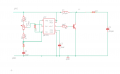
Bit of a long shot and a very general question. I designed a boost converter circuit with the usual topology. The inductance value was 160 mircroH, capacitance 150 microF, a normal silicon diode and a TIP 31A transistor. The DC supply inputted 10 V and provided an output voltage (measured across the capacitance) of 21 V. As soon as I added any resistance value, the voltage measured across the load was no longer larger than input voltage. A full variation of duty cycles were used for the PWM signal going into the transistors base, but had no effect on boosting the voltage.
A side note, the 555 timer is providing the PWM signal and the variable resistor allows for change with the duty cycle.
In the image the connections aren't quite right regarding the PWM generator, but just know that it did supply the correct signal.
Is there a reason my boost converter works with no resistive load and does not when a resistive load is applied?
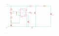
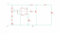
Attachments
-
 273.4 KB Views: 17